Outlet collector of vacuum oil filter

A vacuum oil filter and collector technology, which is applied to containers, motor vehicles, large containers, etc., can solve the problem of further limiting the storage of clean oil

Inactive Publication Date: 2021-09-14
泰州市宏泰电力设备有限公司
View PDF7 Cites 0 Cited by
  • Summary
  • Abstract
  • Description
  • Claims
  • Application Information

AI Technical Summary

Problems solved by technology

[0002] Vacuum oil purifier, also known as vacuum high-efficiency oil filter, oil filter, and oil purifier, has the characteristics of small size, light weight, convenient movement, low working noise, long continuous working time, stable performance, and convenient operation. The oil purifier on the machine generally includes a vacuum heating tank fine filter, condenser, primary filter, water tank, vacuum pump, oil discharge pump and electrical cabinet. Its working principle is that the vacuum pump pumps out the air in the vacuum tank to form a vacuum. Under the action, it enters the primary filter through the inlet pipe, removes larger particles, and then enters the heating tank. After heating, the oil at 40-75 °C passes through the automatic oil drift valve. This valve automatically controls the amount of oil entering the vacuum tank. Balanced in and out, the heated oil rotates rapidly through the spray wings to separate the oil into a semi-mist, the water in the oil evaporates rapidly into water vapor and is continuously sucked into the condenser by the vacuum pump, and the water vapor entering the condenser is cooled Then return to the original water to release, the oil in the vacuum heating tank is discharged into the fine filter by the oil discharge pump, and the particulate impurities are filtered out through the oil filter paper or filter element, so that the vacuum oil filter can quickly remove impurities, water, and gas in the oil. The whole process, so that the clean oil is discharged from the oil outlet, but the vacuum oil filter on the market will produce a certain vibration when it is working. The existence of vibration will make the position of the vacuum oil filter change when it is working. Therefore, it is necessary to design a structure to ensure the stability of the vacuum oil filter when it is working.
[0003] In the prior art, in a Chinese patent document with the application publication number CN201920571299.4, a vacuum oil filter is described, and the vacuum oil filter is disclosed, but the disadvantage is that no further measures have been made for the storage of clean oil. Restrictions and optimization suggestions. During the use of the oil filter unit, the filter oil discharged from the oil discharge pump must be manually handled and stored. Due to the material of the engine oil, there are certain requirements for the storage environment, which brings great harm to people's use process. There are certain adverse effects, in order to solve this problem, we propose a vacuum oil filter outlet collector

Method used


Image

  • Outlet collector of vacuum oil filter
  • Outlet collector of vacuum oil filter
  • Outlet collector of vacuum oil filter

Examples


specific Embodiment 1

[0028] This embodiment is an outlet collector of a vacuum oil filter.

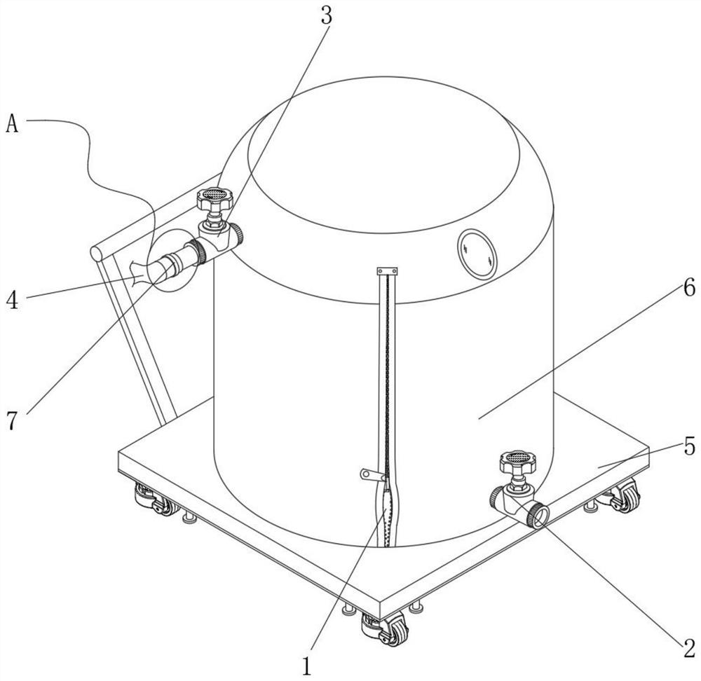
[0029] like Figure 1-5 As shown, an outlet collector of a vacuum oil filter includes an oil storage tank 1, the lower section of the oil storage tank 1 is provided with an oil outlet valve 2, and the upper section of the oil storage tank 1 is provided with an oil inlet valve 3, and the oil inlet valve One end of 3 is provided with an oil discharge pipe 4, the overall outer wall of the oil storage tank 1 is sleeved with a heat preservation mechanism 6, and the outer surface of the lower end of the oil storage tank 1 is provided with a handling mechanism 5, and between the oil inlet valve 3 and the oil discharge pipe 4 is provided with a heat preservation mechanism 6. Connection mechanism 7.

[0030] The oil storage tank 1 is integrated with the oil outlet valve 2 and the oil inlet valve 3. One end of the oil inlet valve 3 is detachably connected to the oil discharge pipe 4 through the connecting mechanism...

specific Embodiment 2

[0033] This embodiment is an embodiment of a conveying mechanism for an outlet collector of a vacuum oil filter.

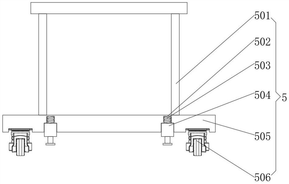
[0034] like figure 1 , 2 As shown, a handling mechanism for the outlet collector of a vacuum oil purifier, the handling mechanism 5 includes a push handle 501, an installation groove 502, an installation stud 503, a cylinder 504, a fixed base 505, a universal wheel 506, and the fixed base 505. The outer surface of the upper end is fixedly connected with the outer surface of the lower end of the oil storage tank 1, the push handle 501 is located on the outer surface of the rear end of the fixed base 505 and is welded to it, and the four universal wheels 506 are based on the central rectangular array of the outer surface of the lower end of the fixed base 505 and All of them are fixedly connected to it, and the four installation slots 502 are all opened on the outer surface of the lower end of the fixed base 505 and are based on the central rectangular array of the...

specific Embodiment 3

[0036] This embodiment is an embodiment of a heat preservation mechanism for an outlet collector of a vacuum oil filter.

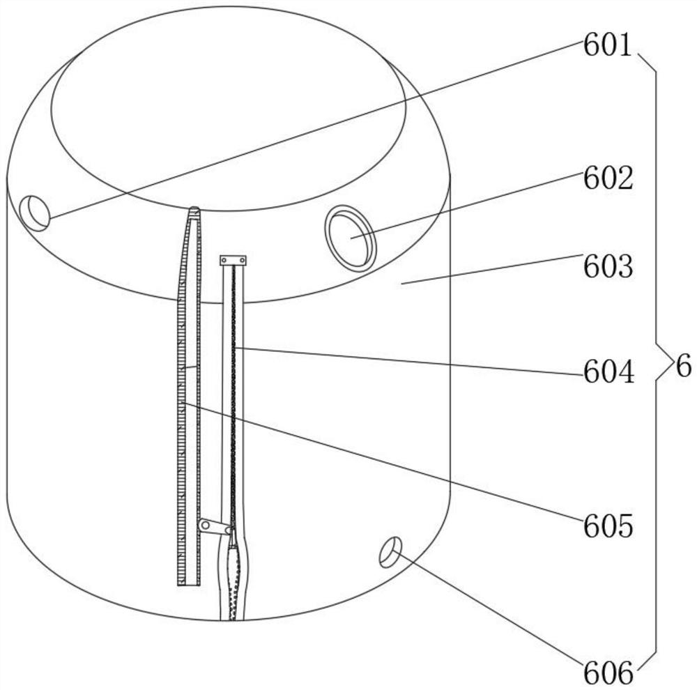
[0037] like figure 1 , 3 As shown, a heat preservation mechanism for an outlet collector of a vacuum oil purifier, the heat preservation mechanism 6 includes a first valve hole 601, a sight glass hole 602, a heat preservation sleeve 603, a zipper 604, a heat preservation material 605 and a second valve hole 606. The overall structure of the sleeve 603 matches the structure of the oil storage tank 1. The first valve hole 601 and the sight glass hole 602 are opened in the upper section of the thermal insulation sleeve 603, and the first valve hole 601 is located on one side of the sight glass hole 602. The second valve hole 601 The hole 606 is opened in the lower section of the heat preservation cover 603 , the zipper 604 is opened on the outer surface of the front end of the heat preservation cover 603 , and the heat preservation cover 603 is opened and cl...


PUM


Abstract

The invention discloses an outlet collector of a vacuum oil filter, which comprises an oil storage tank, wherein an oil outlet valve is arranged on the lower section of the oil storage tank, an oil inlet valve is arranged on the upper section of the oil storage tank, an oil discharge pipe is arranged at one end of the oil inlet valve, the whole outer wall of the oil storage tank is sleeved with a heat preservation mechanism, a carrying mechanism is arranged on the outer surface of the lower end of the oil storage tank, and a connecting mechanism is arranged between the oil inlet valve and the oil discharge pipe. According to the outlet collector of the vacuum oil filter, through the arranged carrying mechanism, an oil storage tank is convenient to carry, the working efficiency is effectively improved, through the arranged heat preservation mechanism, heat preservation cotton can be adopted as a base material of a heat preservation material, the heat preservation cotton has the excellent performance of softness, bending and winding resistance, cold resistance, heat resistance, flame retardance, water resistance, low heat conductivity coefficient, shock absorption, sound absorption and the like, the use performance of the oil storage tank is further improved, manpower is indirectly saved through the arranged connecting mechanism, and better use prospects are brought.

Description

technical field [0001] The invention relates to the field of vacuum oil filters, in particular to an outlet collector of a vacuum oil filter. Background technique [0002] Vacuum oil purifier, also known as vacuum high-efficiency oil purifier, oil purifier, and oil purifier, has the characteristics of small size, light weight, convenient movement, low working noise, long continuous working time, stable performance, and convenient operation. The oil filter above generally includes a vacuum heating tank fine filter, a condenser, a prefilter, a water tank, a vacuum pump, an oil drain pump and an electrical cabinet. Under the action, it enters the pre-filter through the inlet pipe, removes larger particles, and then enters the heating tank. After heating, the oil at 40-75 °C passes through the automatic oil float valve, which automatically controls the amount of oil entering the vacuum tank. In and out balance, the heated oil is separated into a semi-mist by the rapid rotation ...

Claims


Application Information

Patent Timeline
Patent Type & Authority Applications(China)
IPC IPC(8): B01D35/00B65D90/54B65D88/54B65D90/06B62B3/00B62B5/04
CPCB01D35/00B65D90/54B65D88/54B65D90/06B62B3/00B62B5/049
Inventor 戚尤龙
Owner 泰州市宏泰电力设备有限公司
Why Eureka
Try Eureka