
Boiler desulfurization and denitrification device

A desulfurization and denitrification, boiler technology, applied in the field of desulfurization and denitrification, can solve the problems of insufficient flue gas treatment, unfavorable treatment liquid full absorption, high flue gas flow rate, etc.

Pending Publication Date: 2021-09-14
杨显涛
View PDF6 Cites 3 Cited by
  • Summary
  • Abstract
  • Description
  • Claims
  • Application Information

AI Technical Summary

Problems solved by technology

[0006] Aiming at the deficiencies of the prior art, the present invention provides a boiler desulfurization and denitrification device, which solves the problem that traditional desulfurization and denitrification equipment directly processes flue gas, and some nitrogen oxides and sulfur oxides are adsorbed in particulate impurities such as dust, which is not conducive to The full absorption of the treatment liquid and the high flow rate of the flue gas during the desulfurization and denitrification process cannot ensure the full treatment of the flue gas

Method used


Image

  • Boiler desulfurization and denitrification device
  • Boiler desulfurization and denitrification device
  • Boiler desulfurization and denitrification device

Examples


Embodiment 1

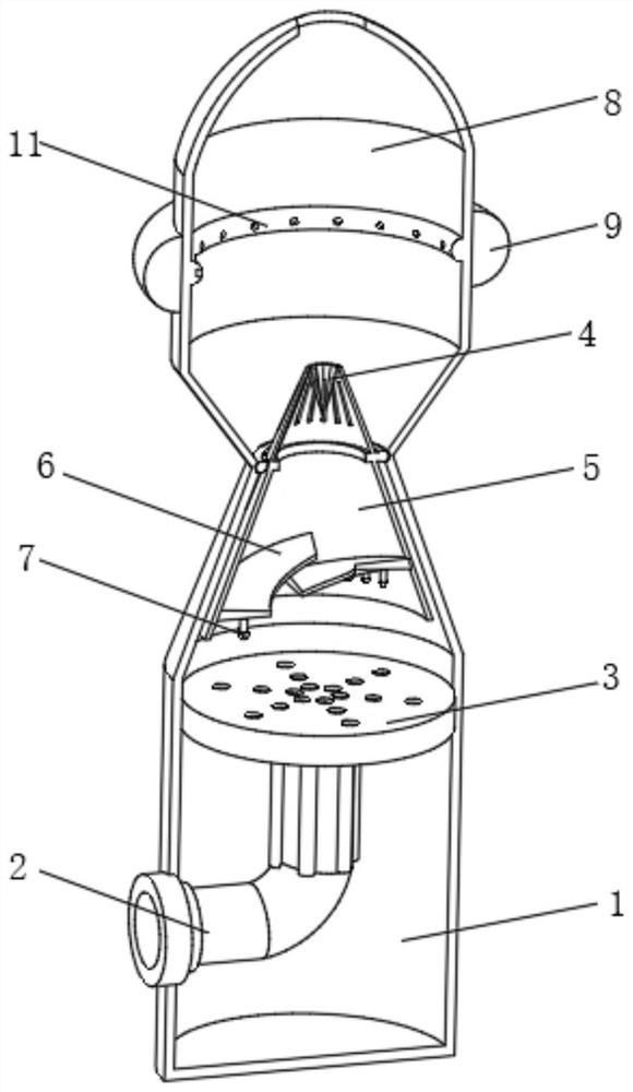
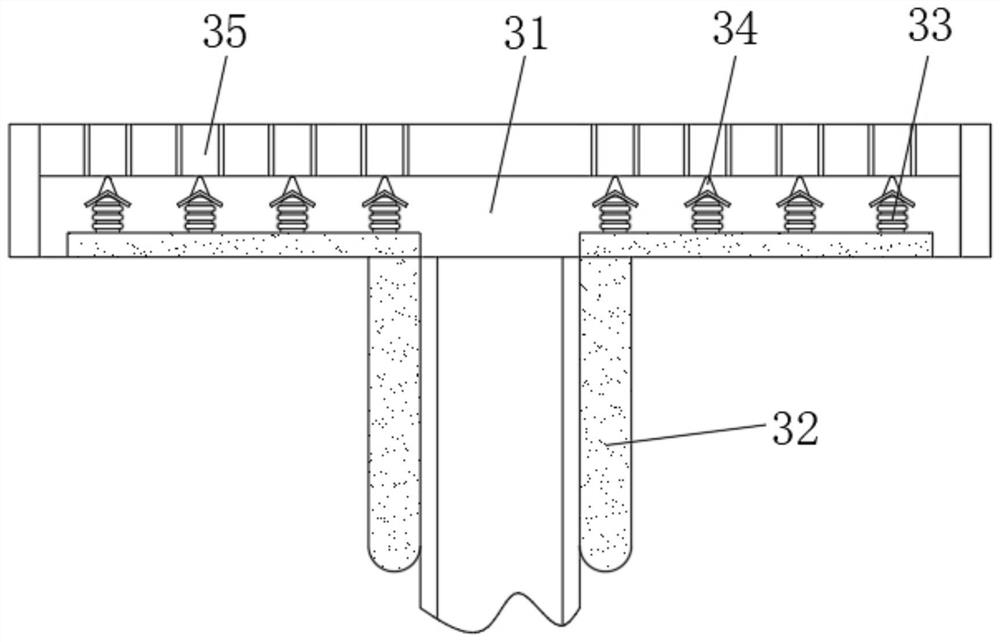
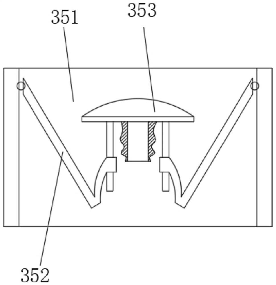
[0036] Such as Figure 1-3 As shown, the present invention provides a technical solution: a boiler desulfurization and denitrification device, including a processing bottom frame 1, and the side of the processing bottom frame 1 near the bottom is fixedly connected with an internal through pipe 2, and the internal through pipe 2 is located at the processing bottom frame 1 One end of the interior is fixedly connected with an adjustment and dredging mechanism 3, and the top of the processing bottom frame 1 is rotatably connected with a dispersing mechanism 4, and the lower part of the dispersing mechanism 4 is fixedly connected with a conduction cone groove 5, and the inner surface of the conduction cone groove 5 near the bottom is uniformly fixedly connected with The buffer fan 6, the bottom surface of the buffer fan 6 is evenly and fixedly connected with the grasping mechanism 7, the top of the processing bottom frame 1 is fixedly connected with the processing top groove 8, and ...

Embodiment 2

[0041] Such as Figure 4-6 As shown, on the basis of Embodiment 1, the present invention provides a technical solution: a boiler desulfurization and denitrification device, the dispersing mechanism 4 includes a movable slider 41, and the movable slider 41 is connected to the internal test of the bottom frame 1 for rotation, The inner side of the movable slider 41 is fixedly connected with a limiting cone plate 42 , and the surface of the joint between the limiting cone plate 42 and the movable slider 41 is uniformly provided with a liquid guiding port 43 . Most of the sprayed treatment liquid flows to 43 on the surface of 42 to realize the directional flow of the treatment liquid and prevent the treatment liquid from entering the air duct and flowing into the boiler.

[0042] Dispersion passages 44 are uniformly provided on the outer surface of the confinement cone plate 42 , and adjustment movable assemblies 45 are rotatably connected to positions inside the confinement cone ...

Embodiment 3

[0046] Such as Figure 7 As shown, on the basis of Embodiment 1 and Embodiment 2, the present invention provides a technical solution: a boiler desulfurization and denitrification device, the grabbing mechanism 7 includes a limiting top plate 71, and the top of the limiting top plate 71 is fixed to the buffer fan 6 Connecting and restricting the rotation of the bottom of the top plate 71 is connected with a rotating strut 72 , and the bottom surface of the rotating strut 72 is connected with a guiding splint 73 for uniform rotation.

[0047] A magnetic block 74 is fixedly connected to the top of the rotating pole 72 and corresponding to the guide clamping plate 73 , and a grasping filter plate 75 is connected to limit the uniform rotation of the outer side of the top plate 71 . The flow velocity of the flue gas is converted into a rotational force, and through the magnetic repulsion between the filter holes 74 and 75, the periodic up and down swing of the 75 is realized to inc...


PUM


Abstract

The invention discloses a boiler desulfurization and denitrification device, which comprises a treatment bottom frame, wherein the side, which is close to the lower portion, of the treatment bottom frame is fixedly communicated with an inner through pipe, the end, which is located in the treatment bottom frame, of the inner through pipe is fixedly communicated with an adjusting dredging mechanism, the top end of the treatment bottom frame is rotationally connected with a dispersing mechanism, the lower portion of the dispersing mechanism is fixedly connected with a conduction conical groove, buffer fan blades are evenly and fixedly connected to the surface, which is close to the lower portion, of the interior of the conduction conical groove, grabbing mechanisms are evenly and fixedly connected to the bottom surfaces of the buffer fan blades, a treatment top groove is fixedly connected to the top of the treatment bottom frame, a liquid storage bag is fixedly connected to the middle of the exterior of the treatment top groove, and a treatment spray pipe is fixedly connected to the middle of the interior of the treatment top groove. The invention relates to the technical field of desulfurization and denitrification. According to the boiler desulfurization and denitrification device, the dust filtering effect is achieved, meanwhile, nitric oxide and sulfur oxide are prevented from being doped in dust and discharged, treatment of the nitric oxide and the sulfur oxide is achieved, and the desulfurization and denitrification efficiency and quality are improved.

Description

technical field [0001] The invention relates to the technical field of desulfurization and denitrification, in particular to a boiler desulfurization and denitrification device. Background technique [0002] Flue gas desulfurization and denitrification technology is a boiler flue gas purification technology applied in the chemical industry that produces many nitrogen oxides and sulfur oxides. Nitrogen oxides and sulfur oxides are one of the main sources of air pollution. [0003] For example, the Chinese invention publication number is: CN109499270A, a boiler coal-fired flue gas desulfurization and denitrification device, which relates to the technical field of waste gas treatment. The main points of its technical solution are: including a shell, which is provided with a multi-layer filter plate, and the shell is located below the filter plate A smoke distribution board is provided, and a smoke outlet is opened on the smoke distribution board, and the smoke outlet deviates ...

Claims


Application Information

Patent Timeline
Patent Type & Authority Applications(China)
IPC IPC(8): B01D53/78B01D53/60B01D50/00F23J15/02F23J15/04F23J15/06
CPCB01D53/78B01D53/60F23J15/025F23J15/04F23J15/06B01D2258/0283Y02A50/20
Inventor 不公告发明人
Owner 杨显涛
Learn More