Efficient drying and filtering device for flue gas sampling

A filtering device and high-efficiency technology, applied in the field of high-efficiency drying and filtering devices for flue gas sampling, can solve the problems of large body cavity, insufficient water vapor absorption of discolored silica gel, and exceeding the standard.

Pending Publication Date: 2021-09-14
SUZHOU XIRE ENERGY SAVING ENVIRONMENTAL PROTECTION TECH CO LTD +1
View PDF0 Cites 0 Cited by
  • Summary
  • Abstract
  • Description
  • Claims
  • Application Information

AI Technical Summary

Problems solved by technology

If there is a problem with this type of device, it will cause blockage of the equipment and excessive discharge, which will bring great economic losses and adverse effects to the power plant, so regular inspection and maintenance are required
[0003] The current detection method is generally to extract the flue gas out of the flue for sampling and analysis, but because the flue gas contains a large amount of water vapor, it will cause blockage and corrosion of the flue gas sampler or dust sampler, affecting the measurement efficiency and the use of equipment Therefore, before the flue gas enters the sampler, a flue gas drying and filtering device must be installed, such as figure 1 As shown, the existing drying device uses color-changing silica gel desiccant for drying, that is, put the color-changing silica gel 1 into the drying barrel 2 to absorb moisture, and the drying barrel is divided into two parts, and the air inlets are respectively set 3 and air outlet 4; but the existing drying device has a large volume and is inconvenient to carry, and the large volume will also cause a large internal cavity, and its internal cavity is only divided into two left and right cavities, which will cause The color-changing silica gel in the cavity does not absorb enough water vapor, that is, the color-changing silica gel in the connecting part of the left and right chambers has been absorbed and saturated and turns pink (HR≥50%), and the other part of the color-changing silica gel is still blue or light blue (HR<50%) ), at this time, the flue gas containing water vapor will directly enter the flue gas sampler from the connection part of the saturated cavity, and the flue gas will preferentially enter the sampler from the gas outlet through the connection area of ​​the left and right chambers from the air inlet, As a result, the drying fails, causing the flue gas sampler to be blocked, and the desiccant is also seriously wasted during the sampling process. In addition, the existing drying device does not have a filter, and the color-changing silica gel will burst when it encounters a large amount of water vapor, forming small particles that cause the sampler to be damaged. The clogging will not only increase the cost of measurement, but also affect the sampling efficiency

Method used


Image

  • Efficient drying and filtering device for flue gas sampling
  • Efficient drying and filtering device for flue gas sampling
  • Efficient drying and filtering device for flue gas sampling

Examples


Embodiment Construction

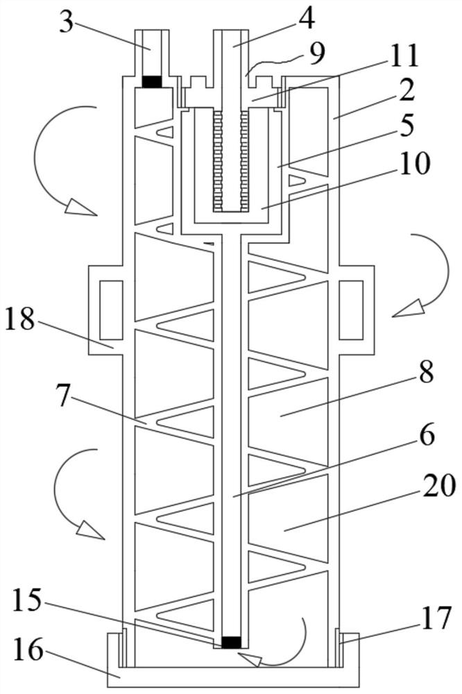
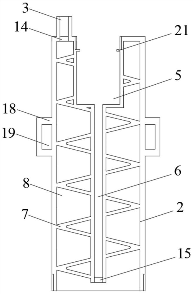
[0021] Such as Figure 2 to Figure 5 As shown, a high-efficiency drying and filtering device for flue gas sampling of the present invention includes a cylindrical drying barrel 2, and the drying barrel 2 is provided with an air inlet 3 and an air outlet 4, and the air outlet 4 is connected to a flue gas sampler Or dust sampler (not shown in the figure), drying barrel 2 is built-in desiccant (not shown in the figure), and desiccant adopts color-changing silica gel, and drying barrel 2 tops are provided with mounting groove 5, and hollow tube 6 After passing through the installation groove 5, it extends into the inside of the drying barrel body 2, and a continuous spiral baffle 7 is provided between the hollow tube 6 and the inner wall of the drying barrel body 2, so that the inner cavity of the drying barrel body 2 is connected to the air inlet 3 The spiral cavity 8 is connected, and the filter element assembly 9 is installed in the installation groove 5. The filter element ass...


PUM

PropertyMeasurementUnit
thicknessaaaaaaaaaa
thicknessaaaaaaaaaa
diameteraaaaaaaaaa

Abstract

The invention provides an efficient drying and filtering device for flue gas sampling. The device is compact in structure, not only can effectively improve the drying efficiency, but also has a better filtering effect, so that the sampling efficiency is improved, and the measurement cost is reduced. The efficient drying and filtering device comprises a drying barrel body. An air inlet and an air outlet are formed in the drying barrel body. A drying agent is arranged in the drying barrel body. A mounting groove is formed in the top end of the drying barrel body, and a hollow pipe penetrates through the mounting groove and then extends into the drying barrel body. A continuous spiral baffle is arranged between the hollow pipe and the inner wall of the drying barrel body so that a spiral cavity communicated with the air inlet can be formed in an inner cavity of the drying barrel body. A filter element assembly is assembled in the mounting groove and comprises a filter element and a filter block installed in the filter element. A through cavity channel in the length direction of the filter block is formed in the filter block, and the outlet end of the through cavity channel is set as an air outlet. Filter holes communicated with the through cavity channel are formed in the surface of the filter block in contact with the filter element.

Description

technical field [0001] The invention relates to the technical field of flue gas drying and filtering, in particular to a flue gas sampling high-efficiency drying and filtering device. Background technique [0002] With the increasingly stringent coal-fired emission standards, coal-fired power plants in my country have generally installed flue gas denitrification, dust removal and desulfurization devices. If there is a problem with this type of device, it will cause blockage of the equipment and excessive discharge, which will bring great economic losses and adverse effects to the power plant, so regular inspection and maintenance are required. [0003] The current detection method is generally to extract the flue gas out of the flue for sampling and analysis, but because the flue gas contains a large amount of water vapor, it will cause blockage and corrosion of the flue gas sampler or dust sampler, affecting the measurement efficiency and the use of equipment Therefore, be...

Claims


Application Information

Patent Timeline
Patent Type & Authority Applications(China)
IPC IPC(8): G01N1/22G01N1/34G01N1/40B01D53/26B01D46/24
CPCG01N1/2258G01N1/34G01N1/4077B01D53/26B01D46/24G01N2001/4088B01D2257/80
Inventor 卢承政刘鹏举何金亮王建阳张庆文
Owner SUZHOU XIRE ENERGY SAVING ENVIRONMENTAL PROTECTION TECH CO LTD
Why Eureka
Try Eureka