
Drafting device for spinning

A drafting device and drafting technology, applied in drafting equipment, textiles, papermaking, spinning machines, etc., can solve the problems of non-concentration of textile threads and inability to adjust the distance of drafting, so as to prevent knotting Effect

Active Publication Date: 2021-09-17
苏州欣丝澜纺织科技有限公司
View PDF6 Cites 0 Cited by
  • Summary
  • Abstract
  • Description
  • Claims
  • Application Information

AI Technical Summary

Problems solved by technology

The Chinese patent application CN201920999293.7 discloses a textile fabric conveying and drafting device. The two sides below the conveying bracket of the utility model are respectively horizontally connected with the feed roller and the discharge roller, and the output end of the draft cylinder is connected with the translation The end of the rack is fixedly connected, and the drafting gear is vertically rotated and connected to the transmission bracket on the upper side of the rotating gear. The transmission bracket outside the drafting gear is fixedly equipped with multiple sets of pulling mechanisms along the radial direction of the drafting gear. The drafting gear A plurality of reciprocating gears are vertically rotated on the outer transmission bracket respectively. The main reciprocating sprocket and the auxiliary reciprocating sprocket are sequentially arranged along the radial direction of the drafting gear. The horizontal rotation is connected to one side of the reciprocating guide plate; the structure design of the invention is reasonable, and it can efficiently and stably continuously draw and process the textile fabric during the transmission process, with a high degree of automation, meeting the needs of processing and use; but the distance of drawing cannot be adjusted, and The textile thread after drafting is not concentrated and prevents the collection of knots

Method used

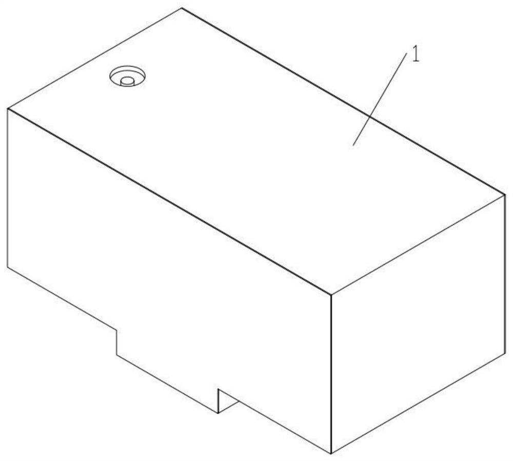

Image

  • Drafting device for spinning
  • Drafting device for spinning
  • Drafting device for spinning

Examples


specific Embodiment approach 1

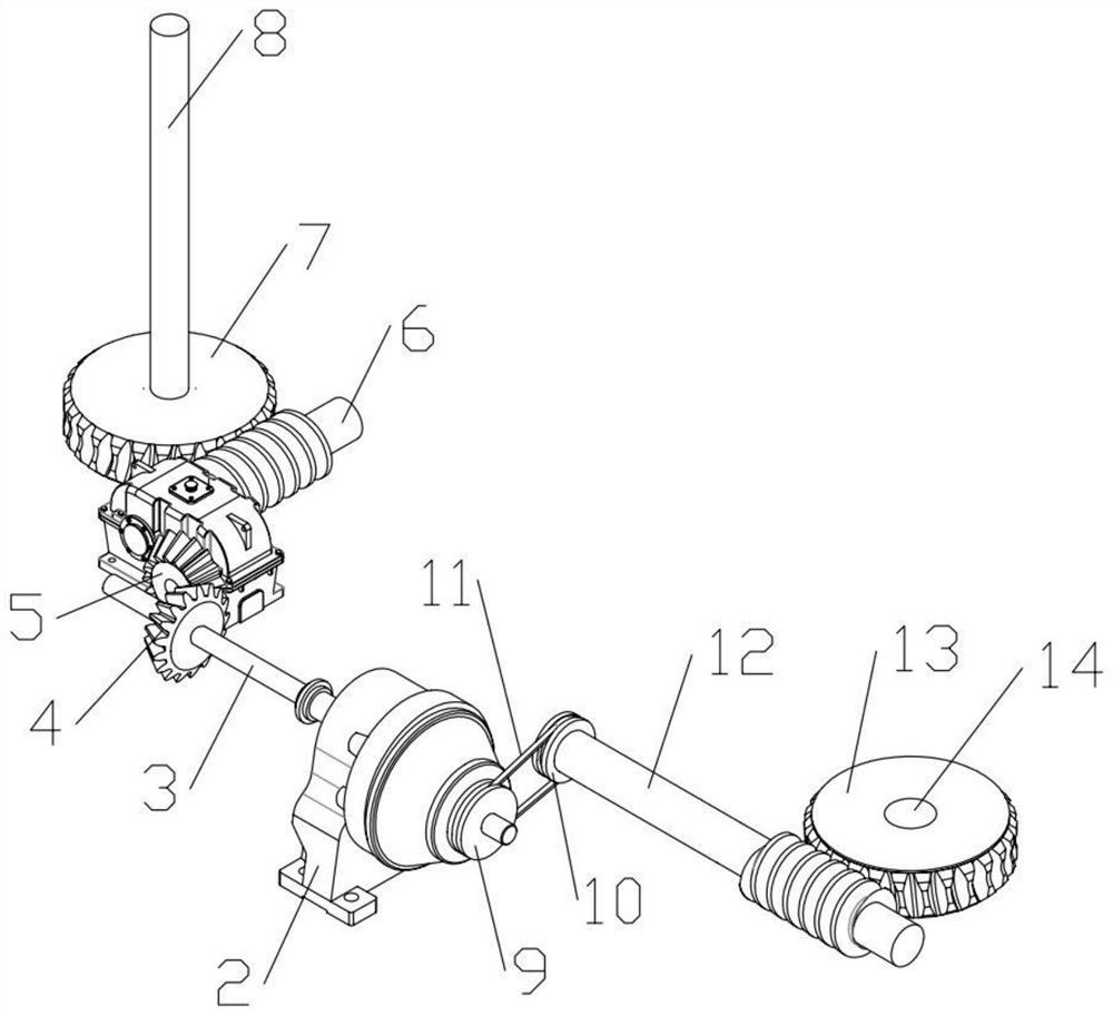
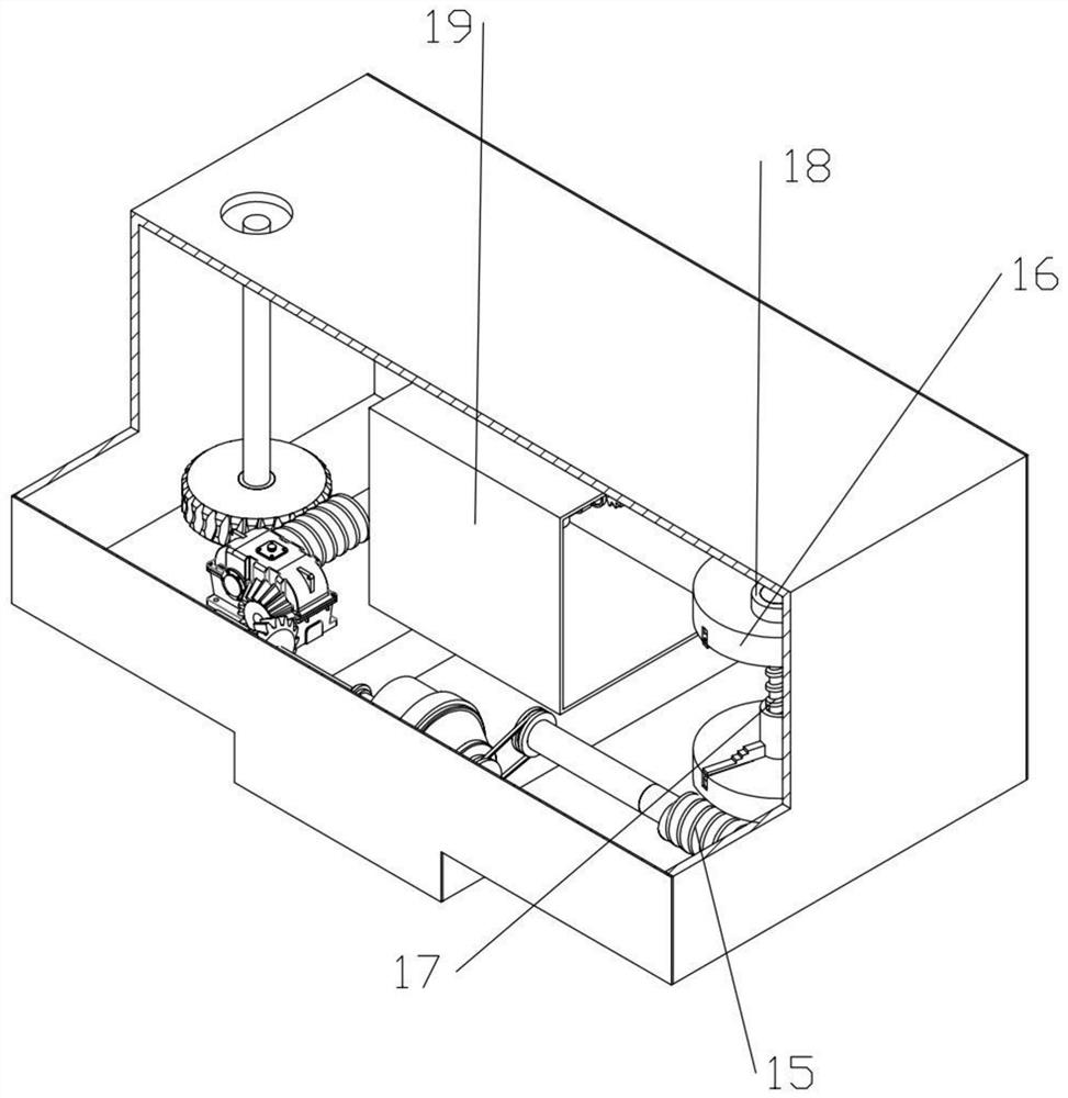
[0034] Combine below Figure 1-18 In order to solve the above-mentioned technical problems, the present invention relates to the technical field of textile machinery, more specifically a drafting device for textiles. The textile thread roll is put in through the groove on the body 1, and the side cover of the body 1 is opened. Put the wire roller into the device, the main shaft of the rolling motor 2 is connected with the reel-3 through a coupling to drive the rotation of the reel-3, and the reel-3 is connected with the helical gear-4 key to make the helical gear-4 rotate accordingly. The first helical gear 4 meshes with the second helical gear 5 to drive the second helical gear 5 to rotate in the opposite direction. The second helical gear 5 is keyed to the input shaft of the reducer to make the reducer run. The shaft device can make the rolling worm one 6 reversely rotate thereupon, and the rolling worm one 6 is meshed with the scrolling turbine one 7 and then drives the rev...

specific Embodiment approach 2

[0035] Combine below Figure 1-18 Describe this embodiment, this embodiment will further explain Embodiment 1, the main shaft of the clamping motor 15-2 is connected with the clamping worm 15-3 through a coupling, so that the rotation of the clamping motor 15-2 can drive the clamping worm The rotation of 15-3, the locking worm 15-3 meshes with the locking turbine 15-4 to further drive the rotation of the locking turbine 15-4, and the locking turbine 15-4 is fixedly connected with the locking shaft 15-5 to drive The rotation of the locking shaft 15-5, the locking shaft 15-5 is fixedly connected with the slide plate 15-6 and then drives the rotation of the slide plate 15-6, and the inclined chute is processed on the slide plate 15-6, when the slide plate 15-6 rotates At the same time, since each group of inclined chute is slidingly connected with the slide bar 15-7, under the rotation of the inclined chute, the movement of the slide bar 15-7 is driven, and the slide bar 15-7 can...

specific Embodiment approach 3

[0036] Combine below Figure 1-18 This embodiment will be described. This embodiment will further explain Embodiment 1. The adjustment plate 18-1 and the upper clamping device 16 are hinged spherically, so that the adjustment plate 18-1 can drive the upper clamping device 16 to move up and down. The positioning device 16 can also be rotated to prevent the rotation of the upper clamping device 16 from affecting the normal movement of the adjusting device 18. When the textile thread is processed, the floating hair on the textile thread will be blown off by a fan. For the sake of environmental protection, energy can be reused The idea is to blow the floating hair with the wind of the fan, and then connect the wind in the device to the air duct with the switch through the upper and lower power slots. When the switch on the air duct of the upper power slot is turned on, the wind blows the wave The blade 18-8, because the force-bearing area of ​​the wave-shaped blade 18-8 generates ...


PUM


Abstract

The invention relates to the technical field of textile machinery, in particular to a drafting device for spinning, and solves the collection problems that the drafting distance cannot be adjusted, and drafted textile threads cannot be concentrated and knotting prevention cannot be realized existing in a patent of a textile fabric conveying drafting device with the Chinese patent application number of CN201920999293.7. The drafting device comprises a machine body; a winding motor is arranged in the machine body; a lower clamping device is arranged on a second winding shaft; the lower clamping device and an upper clamping device are both movably connected with a yarn roller; the upper clamping device is hinged to an adjusting device; and a drafting mechanism is arranged in the machine body. The yarn roller is clamped through the upper clamping device and the lower clamping device, then the drafting mechanism conducts adjustment according to the needed drafting degree, the spinning yarn is drafted, the drafted spinning yarn drives the adjusting device to move through impurity-removed wind on a processing assembly line, the spinning yarn is spirally wound on the yarn roller, and subsequent knotting is prevented.

Description

technical field [0001] The invention relates to the technical field of textile machinery, in particular to a drafting device for textile. Background technique [0002] Yarn refers to a product processed into a certain fineness from various textile fibers, which can be used for weaving, rope making, thread making and embroidery. Fiber or chemical fiber cut fiber) processed by spinning, divided into ring-spun yarn, open-end spinning, self-twisted yarn, etc.; continuous filament yarn, such as natural silk and chemical fiber filament, divided into twisted or untwisted , smooth filament or deformed filament, etc.; short fiber and continuous filament combined yarn, such as polyester-cotton filament core-spun yarn, etc., are formed by merging and twisting two or more single yarns, and the yarns have Certain elasticity, in the yarn production process, the processed yarn needs to be drafted evenly, so that the yarn can reach the required fineness and strength. The Chinese patent ap...

Claims


Application Information

Patent Timeline
Patent Type & Authority Applications(China)
IPC IPC(8): D01H5/44D02J1/22
CPCD01H5/44D02J1/22
Inventor 刘国军
Owner 苏州欣丝澜纺织科技有限公司
Learn More