Mixed gas calorific value metering method

A technology of mixing gas and metering method, applied in the direction of thermal development of materials, etc., can solve the problems of complicated calculation, high equipment investment cost, not meeting the requirements of cost reduction and efficiency increase, etc. Effect

Pending Publication Date: 2021-09-17
BAOTOU IRON & STEEL GRP
View PDF7 Cites 0 Cited by
  • Summary
  • Abstract
  • Description
  • Claims
  • Application Information

AI Technical Summary

Problems solved by technology

However, the simulation calculation of the mixed gas pipeline network is based on the theoretical equation of pipeline hydraulic calculation. According to the configuration conditions of the mixed gas pipeline network, the hydraulic simulation calculation model of the mixed gas pipeline network is established. By inputting the gas flow rate, pressure, temperature, gas composition and The real-time monitoring data of the flow, pressure and temperature of each mixed gas user can be simulated and calculated to obtain the calorific value results of each mixed gas user. The establishment and calculation of the entire model is complicated, and it is necessary to install an analyzer at the outlet of the mixing station to analyze the gas components at the outlet of the mixing station. It can only be realized by testing, and the equipment investment cost is high; ②③The patented technology provides a combustion type calorific value meter, ②It is based on the principle of heat balance to derive the formula to calculate the calorific value of the gas; ③It is by measuring the residual oxygen in the flue gas Calculate the calorific value of gas
The use of ①②③patented technologies requires additional equipment to measure the calorific value of mixed gas, which does not meet the current overall meager profit situation of the steel industry and the cost-increasing requirements

Method used


Image

  • Mixed gas calorific value metering method
  • Mixed gas calorific value metering method
  • Mixed gas calorific value metering method

Examples


Embodiment Construction

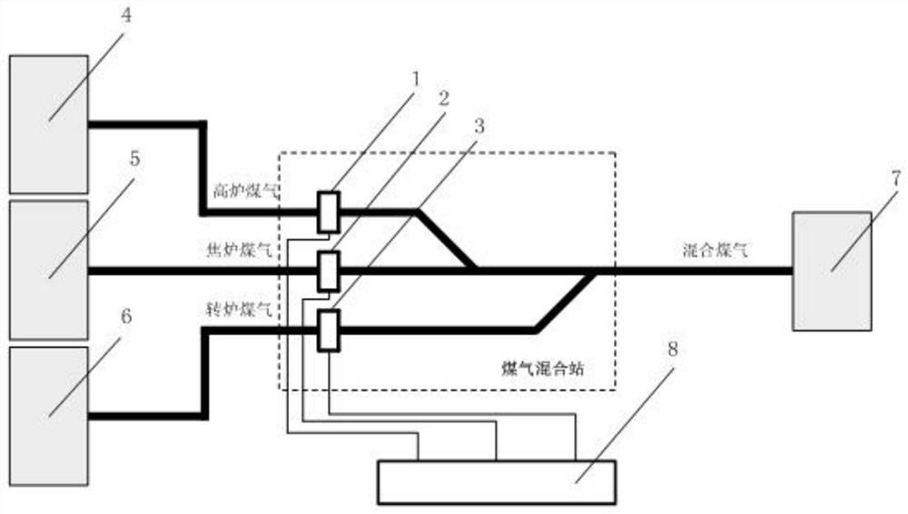
[0026] Such as figure 1 As shown, a method for measuring the calorific value of mixed gas, its main structure includes a blast furnace gas flow meter 1, a coke oven gas flow meter 2, a converter gas flow meter 3, a blast furnace gas cabinet 4, a coke oven gas cabinet 5, a converter Gas cabinet 6 and user 7, PLC or DCS system 8; the blast furnace gas flow meter 1 is a meter installed on the blast furnace gas pipeline before gas mixing; the coke oven gas flow meter 2 It is a measuring instrument installed on the coke oven gas pipeline before gas mixing for measuring the coke oven gas flow rate; the converter gas flow measuring instrument 3 is a measuring instrument installed on the converter gas pipeline before gas mixing for measuring the converter gas flow rate; The blast furnace gas flow meter 1 , the coke oven gas flow meter 2 and the converter gas flow meter 3 all adopt flow temperature and pressure compensation, and the signals are respectively connected to the PLC or DCS ...


PUM


Abstract

The invention discloses a mixed gas calorific value metering method, which comprises the following steps of: respectively accessing signals of a blast furnace gas flow instrument mounted on an original blast furnace gas pipeline, a coke oven gas flow instrument mounted on a coke oven gas pipeline and a converter gas flow instrument mounted on a converter gas pipeline before gas mixing into a PLC (Programmable Logic Controller) or a DCS (Distributed Control System); setting a blast furnace gas theoretical calorific value, a coke oven gas theoretical calorific value and a converter gas theoretical calorific value in the PLC or the DCS system, and calculating the theoretical calorific value of the mixed gas through a formula according to the proportions of the blast furnace gas, the coke oven gas and the converter gas in the mixed gas. The invention aims to provide a mixed gas calorific value metering method, the calorific value of the mixed gas is obtained through a theoretical calculation method on the basis of not increasing detection equipment, the mixing proportion of three kinds of gas is controlled to meet the requirements of steel rolling users, and meanwhile converter gas is fully utilized.

Description

technical field [0001] The invention relates to a method for measuring the calorific value of mixed gas. Background technique [0002] The by-product gas of iron and steel enterprises mainly includes blast furnace gas, coke oven gas and converter gas, and the calorific value of these gases varies greatly. In order to save energy, improve efficiency, and protect the environment, currently blast furnace gas is mainly used for power generation, and converter gas needs to be fully utilized. Since the calorific value of converter gas is lower than the calorific value demand of steel rolling users, it is necessary to mix the three types of gas in a certain volume ratio to form a mixed gas for the user. When mixing, it is necessary to know the calorific value of the mixed gas to control the blending ratio. [0003] Existing mixed gas calorific value measurement technology: [0004] ①Chongqing CCID Thermal Engineering and Environmental Protection Engineering Technology Co., Ltd., ...

Claims


Application Information

Patent Timeline
IPC IPC(8): G01N25/22
CPCG01N25/22
Inventor 杨莉刘雪峰
Owner BAOTOU IRON & STEEL GRP
Why Eureka
Try Eureka