Compression system capable of effectively reducing axial load of fuel assembly and fuel assembly
A fuel assembly and axial load technology, applied in the direction of reactor fuel elements, assembly of fuel elements, reduction of greenhouse gases, etc., can solve problems affecting the structural integrity of fuel assemblies, fuel assembly jumping, etc., to increase thermal margin , Increase the flow rate, improve the effect of safety margin
- Summary
- Abstract
- Description
- Claims
- Application Information
AI Technical Summary
Problems solved by technology
Method used
Image
Examples
Embodiment 1
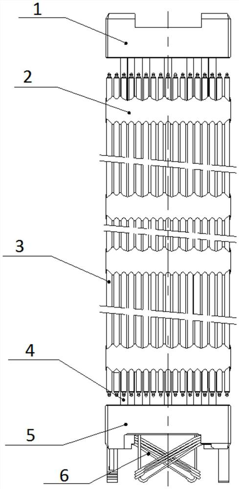
[0038] This embodiment proposes a compression system 6 that can effectively reduce the axial load of the fuel assembly. The compression system 6 is arranged at the lower part of the reactor fuel assembly to provide axial support and positioning for the fuel assembly.
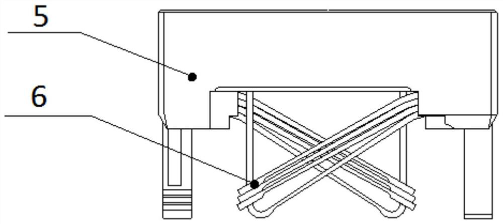
[0039] Such as figure 1 As shown, the compression system 6 is composed of multiple sets of elastic elements installed at the lower end of the lower tube base 5 of the fuel assembly, and provides axial compression and support for the fuel assembly when the fuel assembly is loaded into the reactor.
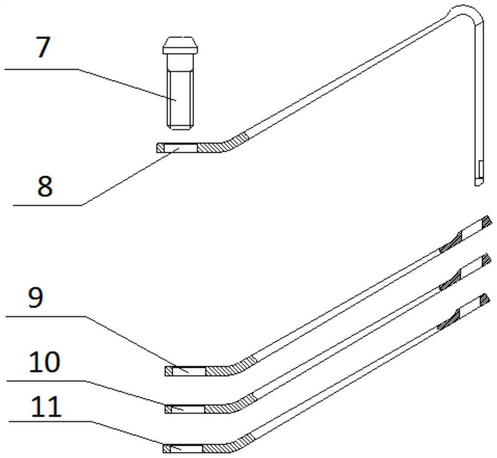
[0040] The pressing system 6 of this embodiment can be realized by leaf springs, coil springs, disc springs, other elastic elements or combinations thereof.
[0041]The stiffness and stroke (range of deformation) of the compression system 6 of this embodiment should be adapted to the weight of the fuel assembly and its operating environment and parameters (temperature, pressure, coolant flow rate, stack cavity height,...
Embodiment 2
[0046] The difference between this embodiment and Embodiment 1 is that the elastic element used in the pressing system 6 of this embodiment is a helical spring, that is, the pressing system 6 of this embodiment consists of a group of helical springs installed at the lower end of the lower pipe seat 5 of the fuel assembly. Each set of helical springs is composed of one or several concentric helical springs; each set of helical springs can be provided with a guide device, and the compression load generated by the helical springs provides support for the bottom of the fuel assembly.
Embodiment 3
[0048] The difference between this embodiment and Embodiment 1 is that the elastic element used in the compression system 6 of this embodiment is a disc spring, that is, the compression system 6 of this embodiment is composed of an array of disc springs installed at the lower end of the lower pipe seat 5 , each group of disc springs is composed of one or several overlapping disc springs; each group of disc springs can be provided with a guide device, and the compression load generated by the disc springs provides support for the bottom of the fuel assembly.
PUM
 Abstract
Description
Claims
Application Information
 - R&D
- Intellectual Property
- Life Sciences
- Materials
- Tech Scout
- Unparalleled Data Quality
- Higher Quality Content
- 60% Fewer Hallucinations
Browse by: Latest US Patents, China's latest patents, Technical Efficacy Thesaurus, Application Domain, Technology Topic, Popular Technical Reports.
© 2025 PatSnap. All rights reserved.Legal|Privacy policy|Modern Slavery Act Transparency Statement|Sitemap|About US| Contact US: help@patsnap.com


