Method and device for prolonging service life of surface of friction pair of part
A technology of friction pairs and parts, which is applied in the field of laser surface engineering, can solve the problems of micro pits and micro pits that are prone to cracks and wear debris easy to block, and achieve the effects of improving fatigue resistance, prolonging service life, and efficient removal
- Summary
- Abstract
- Description
- Claims
- Application Information
AI Technical Summary
Problems solved by technology
Method used
Image

Examples
Embodiment Construction
[0037] Below in conjunction with specific implementation example, above-mentioned scheme is described further, and preferred embodiment of the present invention is described in detail as follows:
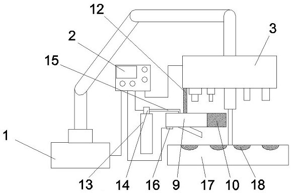
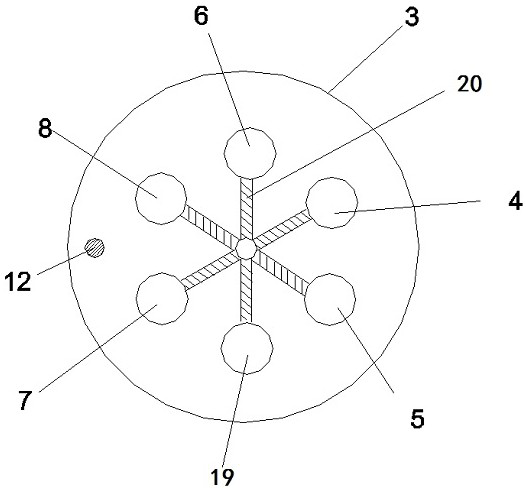
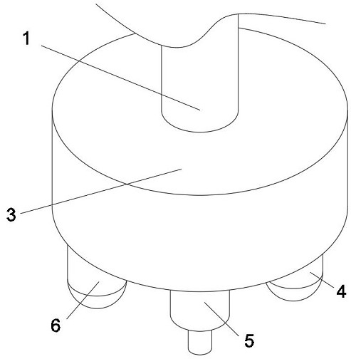
[0038] refer to figure 1 , figure 2 and image 3 , a device for prolonging the service life of the surface of the friction pair of parts, including a mechanical arm 1, a computer 2 is provided on one side of the mechanical arm 1, and a circular working head is provided at one end of the mechanical arm 1, which is used to convert the operating instrument. As required, the computer 2 controls the mechanical arm 1 to move the working instrument head into the near center of the circular working head 3 along the screw drive guide rail 20, so that it can work with the micro-dimple surface of the sample. One end of the mechanical arm 1 is provided with a circular working head 3, the circular working head includes six screw drive guide rails 20, the six screw drive guide rails 20 are res...
PUM
| Property | Measurement | Unit |
|---|---|---|
| Diameter | aaaaa | aaaaa |
Abstract
Description
Claims
Application Information
 - R&D
- Intellectual Property
- Life Sciences
- Materials
- Tech Scout
- Unparalleled Data Quality
- Higher Quality Content
- 60% Fewer Hallucinations
Browse by: Latest US Patents, China's latest patents, Technical Efficacy Thesaurus, Application Domain, Technology Topic, Popular Technical Reports.
© 2025 PatSnap. All rights reserved.Legal|Privacy policy|Modern Slavery Act Transparency Statement|Sitemap|About US| Contact US: help@patsnap.com