Optical module with external optical receiving device

A technology for optical receiving devices and optical receiving components, applied in the field of optical communication, can solve the problems of complex signal circuit design and layout, extremely high process assembly requirements, and difficult maintenance and processing, so as to achieve larger layout space, reduce process difficulty, and save packaging. cost effect

Pending Publication Date: 2021-09-21
GUANGDONG RUIGU OPTICAL NETWORK COMM CO LTD
View PDF0 Cites 0 Cited by
  • Summary
  • Abstract
  • Description
  • Claims
  • Application Information

AI Technical Summary

Problems solved by technology

[0004] However, in the existing optical modules, the light-emitting components and the light-receiving components are built-in and packaged in the casing, which makes the design and layout of the signal circuit extremely complicated, high in cost, and has extremely high requirements for process assembly, which is not easy to maintain and handle

Method used


Image

  • Optical module with external optical receiving device
  • Optical module with external optical receiving device
  • Optical module with external optical receiving device

Examples


Embodiment Construction

[0032] In order to make the purpose, features and advantages of the present invention more obvious and understandable, the technical solutions in the embodiments of the present invention will be clearly and completely described below in conjunction with the accompanying drawings in the embodiments of the present invention. Obviously, the following description The embodiments are only some of the embodiments of the present invention, but not all of them. Based on the embodiments of the present invention, all other embodiments obtained by persons of ordinary skill in the art without making creative efforts belong to the protection scope of the present invention.

[0033] In the description of the present invention, it is to be understood that when a component is said to be "connected" to another component, it may be directly connected to the other component or there may be an intervening component at the same time. When a component is said to be "set on" another component, it ca...


PUM

PropertyMeasurementUnit
electrical resistanceaaaaaaaaaa

Abstract

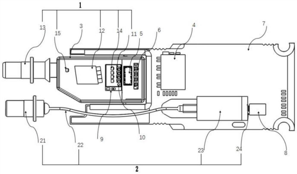
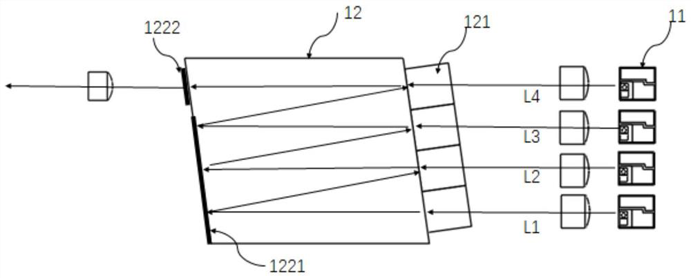
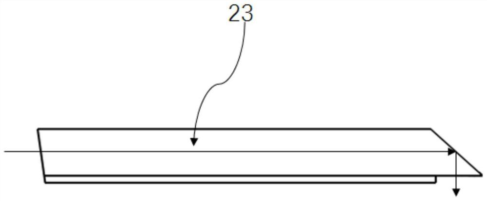
The invention relates to the technical field of optical communication, in particular to an optical module with an external optical receiving device. The optical module comprises a light emitting assembly, a light receiving assembly, a shell and a control unit, wherein the light emitting assembly is arranged in the shell, and the light emitting assembly and the light receiving assembly are electrically connected with the control unit; the light emitting assembly comprises a laser unit, an optical multiplexer and a first adapter which are sequentially arranged in an optical axis direction, and the optical multiplexer is used for emitting light emitted by the laser unit into the first adapter; and the light receiving assembly comprises a second adapter, a light conduction piece, an array waveguide grating and a photoelectric detector unit which are sequentially arranged in the optical axis direction, the second adapter is used for inputting external light to the array waveguide grating through the light conduction piece, and the array waveguide grating converts input external light into a plurality of light splitting signals and then emits the light splitting signals into the photoelectric detector unit. According to the invention, the light emitting assembly and the light receiving assembly are separated, the layout space of the optical module is enlarged, and process difficulty is reduced.

Description

technical field [0001] The invention relates to the technical field of optical communication, in particular to an optical module with an external optical receiving device. Background technique [0002] The 100G optical module is an optical module product born to adapt to the trend of the network market gradually developing from 10G to 40G and 100G, with a transmission rate of 100G. 100G optical modules play a vital role in building 100G network systems. [0003] With the development of the optical communication industry, the market demand for 100G optical modules continues to expand. The current mainstream 100G optical module is a transmission module based on single-mode coarse wavelength division multiplexing technology. The 100G optical module is LR4 type and uses 4 channels of 25Gbps signals. The optical fiber transceiver adopts single-mode laser light source, adopts LC duplex interface, and each optical fiber supports signal transmission of 4 long-wave bands. [0004]...

Claims


Application Information

Patent Timeline
Patent Type & Authority Applications(China)
IPC IPC(8): G02B6/42
CPCG02B6/4204G02B6/4215G02B6/4246G02B6/4214G02B6/4274G02B6/428
Inventor 丁植肖磊罗榴阳曦
Owner GUANGDONG RUIGU OPTICAL NETWORK COMM CO LTD
Why Eureka
Try Eureka