Motion planning method for pushing mechanism of hydraulic support and scraper conveyor

A technology of scraper conveyor and hydraulic support, which is applied in the fields of mine roof support, earthwork drilling, and special data processing applications, etc. It can solve problems such as redundant calculations, obstacles to the coordinated advancement of virtual fully mechanized mining faces, and difficulties, so as to avoid calculations. process, realize real-time and motion visualization, and the effect of reasonable motion

Pending Publication Date: 2021-09-21
TAIYUAN UNIV OF TECH
View PDF10 Cites 1 Cited by
  • Summary
  • Abstract
  • Description
  • Claims
  • Application Information

AI Technical Summary

Problems solved by technology

[0006] In the above method, when obtaining the motion parameters of each structure of the pushing mechanism, it is necessary to install several electronic components such as sensors and cameras. Considering the influence factors such as underground space, light limitation, and electromagnetic interference wireless signals, as well as the limitation of the number of hydraulic supports, It is difficult to obtain the angle and distance of the pushing mechanism by using electronic components, and it does not take into account the motion characteristics of the moving mechanism in real situations, and it requires complicated calculations during theoretical analysis. The process of determining the optimal solution of the floating connection mechanism complex
At present, on the issue of coordinated propulsion of the hydraulic support and the scraper conveyor, when the hydraulic support pushes the scraper conveyor, there is a lot of free movement in the pushing mechanism, which hinders the coordinated advancement of the virtual fully mechanized mining face. The movement is planned, and the mapping relationship between the hydraulic support and the scraper conveyor in the virtual environment and the real underground environment is established

Method used


Image

  • Motion planning method for pushing mechanism of hydraulic support and scraper conveyor
  • Motion planning method for pushing mechanism of hydraulic support and scraper conveyor
  • Motion planning method for pushing mechanism of hydraulic support and scraper conveyor

Examples


Embodiment Construction

[0046] In order to have a clearer understanding of the technical features, purposes and effects of the present invention, the specific implementation manners of the present invention will now be described in detail with reference to the accompanying drawings.

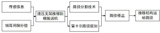
[0047] Such as figure 1 As shown, the present invention provides a method for motion planning of the pushing mechanism of the hydraulic support and the scraper conveyor, including:

[0048] When the pushing mechanism of the hydraulic support and the scraper conveyor starts to move, the lug clearance compensation method between the hydraulic support and the scraper conveyor is used to eliminate the lug gap between the hydraulic support and the scraper conveyor, and the real-time sensing information of the embedded sensor on the hydraulic support is obtained;

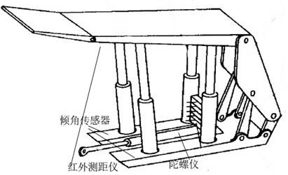
[0049] Wherein, the embedded sensor includes at least an infrared range finder installed on the base of the hydraulic support, an inclination sensor embedded on bo...


PUM


Abstract

The invention provides a motion planning method for a pushing mechanism of a hydraulic support and a scraper conveyor, which comprises the following steps: embedding related sensors in the hydraulic support to obtain real-time information, and after a coal mining machine cuts, planning the motion of each structure of the pushing mechanism by using a Cartesian path planning method after applying a path segmentation technology; obtaining a motion law of the three-dimensional coordinates based on the key points of each structure relative to the time dimension, and carrying out processing by using a Gaussian filtering correction method to obtain a final correction track; and applying the obtained motion rule to a coal seam created by Unity3D and a virtual coal machine equipment joint simulation system, accessing real-time sensing information to a virtual environment through an interface reserved in Unity3D for joint planning, and finally obtaining planned motion of the pushing mechanism. According to the invention, the movement of each structure of the pushing mechanism can be planned, and the mapping relation between the cooperative propulsion of the hydraulic support and the scraper conveyor in the virtual environment and the real underground environment is established.

Description

technical field [0001] The invention relates to the technical field of path planning, in particular to a motion planning method for a pushing mechanism of a hydraulic support and a scraper conveyor. Background technique [0002] Intelligent mining is the goal of modern coal mining, and virtual mining is one of the keys to realize intelligent mining. The floating connection mechanism of the hydraulic support and the scraper conveyor has multiple degrees of freedom of spatial movement, and its movement plays an important role in the coordinated advancement of the virtual fully mechanized mining face. The movement of the connected mechanism is planned. [0003] The application number is CN202010102529.X, which discloses a posture description method for the floating connection mechanism of hydraulic support and scraper conveyor, which converts the pushing mechanism into an industrial robot model, and determines the motion parameters of the floating connection mechanism based on...

Claims


Application Information

Patent Timeline
Patent Type & Authority Applications(China)
IPC IPC(8): G06F30/20E21D23/18E21D23/12
CPCG06F30/20E21D23/12E21D23/18
Inventor 谢嘉成李素华王学文任芳崔涛焦秀波蔡宁童梦瑶
Owner TAIYUAN UNIV OF TECH
Why Eureka
Try Eureka