
Power divider with port phase shift, design method thereof, and electronic equipment

A power divider and phase shift technology, applied in circuits, electrical components, waveguide devices, etc., can solve the problems of errors, impedance transformation transmission line errors, inability to achieve high characteristic impedance values, etc., and achieve a simple design method and a large working bandwidth. , the effect of increasing the coupling degree

Active Publication Date: 2021-09-21
AEROSPACE INFORMATION RES INST CAS
View PDF8 Cites 0 Cited by
  • Summary
  • Abstract
  • Description
  • Claims
  • Application Information

AI Technical Summary

Problems solved by technology

When designing a multi-level power divider, due to the influence of machining accuracy, there is often a certain error between the actual line width and the theoretical value of the impedance transformation transmission line. The realization of the microstrip line structure
[0004] Specifically, the current power divider has the following technical defects: Affected by the circuit processing accuracy, in the process of designing the impedance transformation line of the multi-level power divider, there is a certain gap between the actual impedance value and the theoretical calculation value achieved by changing the transmission line width. error; when designing the impedance transformation line of a multi-level broadband power divider that requires a high characteristic impedance, the traditional microstrip transmission line structure cannot achieve the high characteristic impedance value required by the theory; the phase shift achieved by using the traditional microstrip coupling line structure Due to the limitation of the coupling degree of the microstrip coupling line structure, the working bandwidth of the phase shifter cannot be further improved, and it cannot be used in some broadband application scenarios.

Method used


Image

  • Power divider with port phase shift, design method thereof, and electronic equipment
  • Power divider with port phase shift, design method thereof, and electronic equipment
  • Power divider with port phase shift, design method thereof, and electronic equipment

Examples


Embodiment Construction

[0047] The essence of the technical solutions of the embodiments of the present application will be explained in detail below in conjunction with the accompanying drawings.

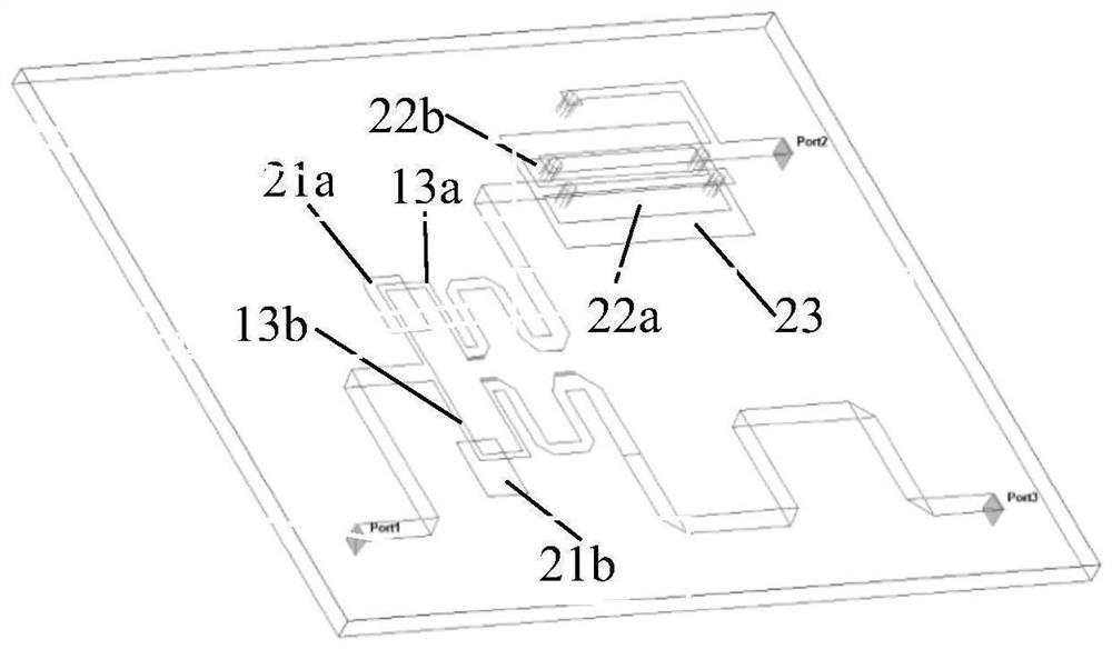
[0048] The embodiment of the present application adopts a multi-stage power divider circuit design and a broadband phase shifter as the design basis, and by loading a defective ground structure, two parts of the circuit structure are cascaded to obtain an overall power divider circuit design with port phase shift. The embodiment of the present application realizes a relatively large working bandwidth, adopts a multi-line layer structure, has a simple design method, and is easy to implement miniaturized and integrated circuit design.

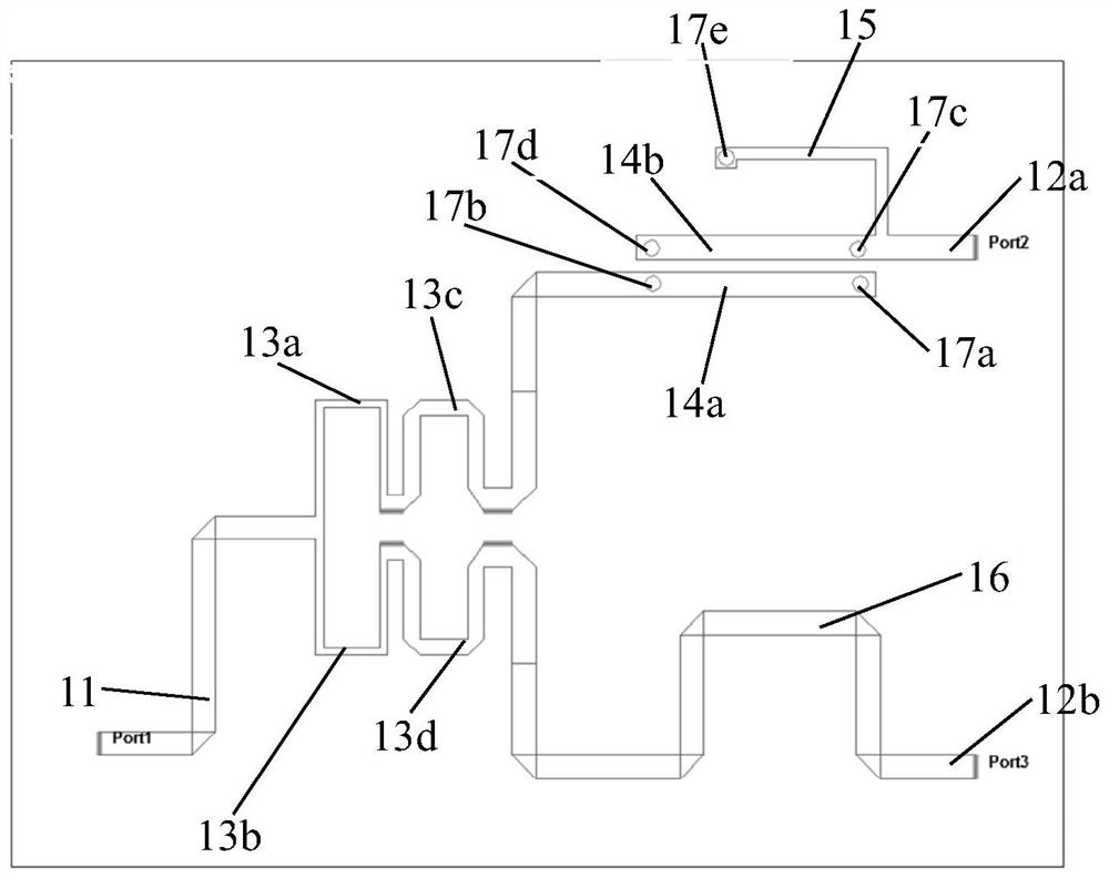
[0049] figure 1 It is a schematic diagram of the composition and structure of the first circuit layer of the power divider with port phase shift in the embodiment of the present application, as shown in figure 1 As shown, the power splitter with port phase shift of the embo...


PUM


Abstract

The invention relates to a power divider with port phase shift, a design method thereof, and electronic equipment. According to the power divider, an input port transmission line is electrically connected with an impedance conversion transmission line, and an output port transmission line is electrically connected with a phase shifter phase reference transmission line and a phase shifter upper coupling line; the impedance conversion transmission line is electrically connected with the phase shifter upper coupling line; the phase shifter half-wavelength transmission line is electrically connected with the phase shifter upper coupling line and is connected with the circuit grounding layer through a via hole; the phase shifter upper coupling line and the phase shifter phase reference transmission line are electrically connected with output port transmission lines respectively; a defected ground structure corresponds to the impedance conversion transmission line and the upper coupling line of the phase shifter in position; and the ground layer coupling line is electrically connected with the phase shifter upper layer coupling line through a via hole formed in the first circuit layer. According to the invention, a multi-line layer structure is realized, the design method is simple, and miniaturization and integration design of the circuit is easy to realize.

Description

technical field [0001] The embodiments of the present application relate to a power splitter, and in particular to a power splitter with a port phase shift, a design method for a power splitter with a port phase shift, and an electronic device. Background technique [0002] A power divider (referred to as a power divider) is a multi-port passive microwave network that divides the input signal power into several equal or unequal signal outputs, and is widely used in power distribution or power synthesis. Ideally, the power divider structure can achieve matching and lossless at all ports of the circuit, and the set port isolation resistance can effectively improve the isolation of the ports, so it is widely used. The power divider is widely used in the feeding system of the radar antenna. The external isolation resistor can effectively improve the circuit isolation. Due to the use of the 1 / 4 wavelength line theory, the amplitude and phase balance of the output port mainly depe...

Claims


Application Information

Patent Timeline
IPC IPC(8): H01P5/16
CPCH01P5/16
Inventor 李霁晨刘开雨李天龙王宇
Owner AEROSPACE INFORMATION RES INST CAS
Features
  • Generate Ideas
  • Intellectual Property
  • Life Sciences
  • Materials
  • Tech Scout
  • Unparalleled Data Quality
  • Higher Quality Content
  • 60% Fewer Hallucinations
Learn More