Communication equipment maintenance device

A technology for communication equipment and fixed boxes, applied to workpiece clamping devices, workbenches, manufacturing tools, etc., can solve problems such as poor mobility, weak scalability, and failures, and achieve the effect of reducing support pressure and ensuring stability

Inactive Publication Date: 2021-09-24
六安保识信息技术有限公司
View PDF0 Cites 2 Cited by
  • Summary
  • Abstract
  • Description
  • Claims
  • Application Information

AI Technical Summary

Problems solved by technology

Wireless communication equipment is mainly wireless AP, wireless network bridge, wireless network card, wireless lightning arrester, antenna and other equipment. The biggest advantage of wired communication equipment is strong anti-interference, high stability, certain confidentiality, fast transmission rate, and unlimited bandwidth. Large; but the wired communication is greatly affected by the environment, the scalability is weak, there is attenuation, the construction is difficult, the mobility is poor, and the cost is high
[0003] At present, communication equipment sometimes breaks down during use and needs to be repaired. Generally, auxiliary maintenance is carried out through communication equipment maintenance platforms. Common communication equipment maintenance platforms on the market have a series of defects, such as communication equipment maintenance. The angle of the communication equipment in the vertical direction is always in a parallel state. It is not possible to adjust the position of the communication equipment to be repaired to an oblique angle, which increases the difficulty of maintenance.

Method used


Image

  • Communication equipment maintenance device
  • Communication equipment maintenance device
  • Communication equipment maintenance device

Examples


Embodiment 1

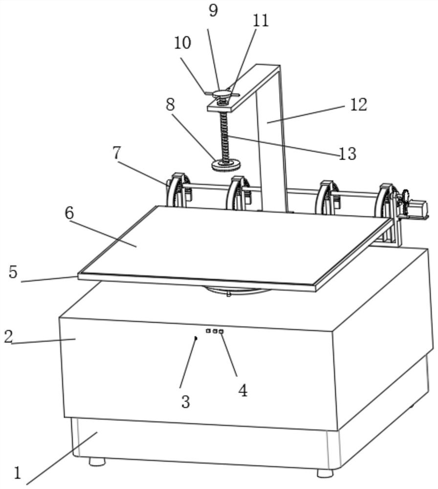
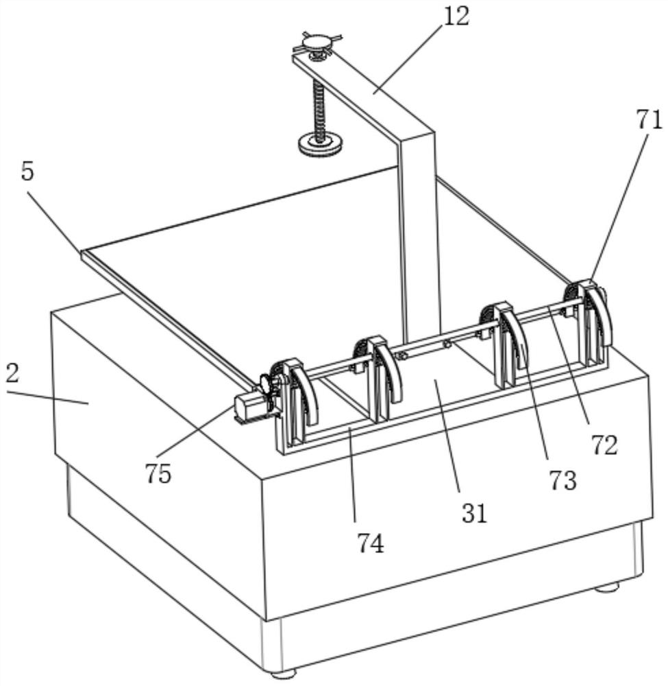
[0035] Such as Figure 1-8A maintenance device for communication equipment is shown, which includes a fixed box body 1. The inner bottom of the fixed box body 1 is connected with a height adjustment mechanism 14 for adjusting the height of the communication equipment. The top of the height adjustment mechanism 14 is connected with the fixed box body. 1. The outer wall of the casing 2 is fitted with a sliding connection. The outer wall of the casing 2 is fixedly connected with a switch 4. The casing 2 is connected with a horizontal rotation structure 3 for adjusting the horizontal rotation of the communication equipment. The rear side wall of the casing 2 Connected with a vertical rotation structure 7 for adjusting the vertical rotation of the communication equipment, the vertical rotation structure 7 includes an n-shaped plate 71, a first rotation rod 72, an arc-shaped tooth plate 73, a U-shaped plate 74, and a first drive motor 75 , the first mounting plate 76, the first ring...

Embodiment 2

[0037] Embodiment 2 is a further improvement to Embodiment 1.

[0038] Such as Figure 1-8 The communication equipment maintenance device shown includes a fixed box body 1, the inner bottom of the fixed box body 1 is connected with a height adjustment mechanism 14 for adjusting the height of the communication equipment, and the top of the height adjustment mechanism 14 is connected with the fixed box body. The outer wall of the body 1 is attached to the casing 2 which is slidingly connected. The outer wall of the casing 2 is fixedly connected with a switch 4. The casing 2 is connected with a horizontal rotation structure 3 for adjusting the horizontal rotation of the communication equipment. The horizontal rotation structure 3 includes a rotation Plate 31, pull ring 32, rotating rod 33, guide ring 34, T-shaped plate 35, steel rope 36, spring 37, first sleeve 38, universal ball 39 and straight sleeve 310, guide ring 34 and straight sleeve 310 and The top of cover box 2 is fixe...

Embodiment 3

[0040] Embodiment 3 is a further improvement to Embodiment 1.

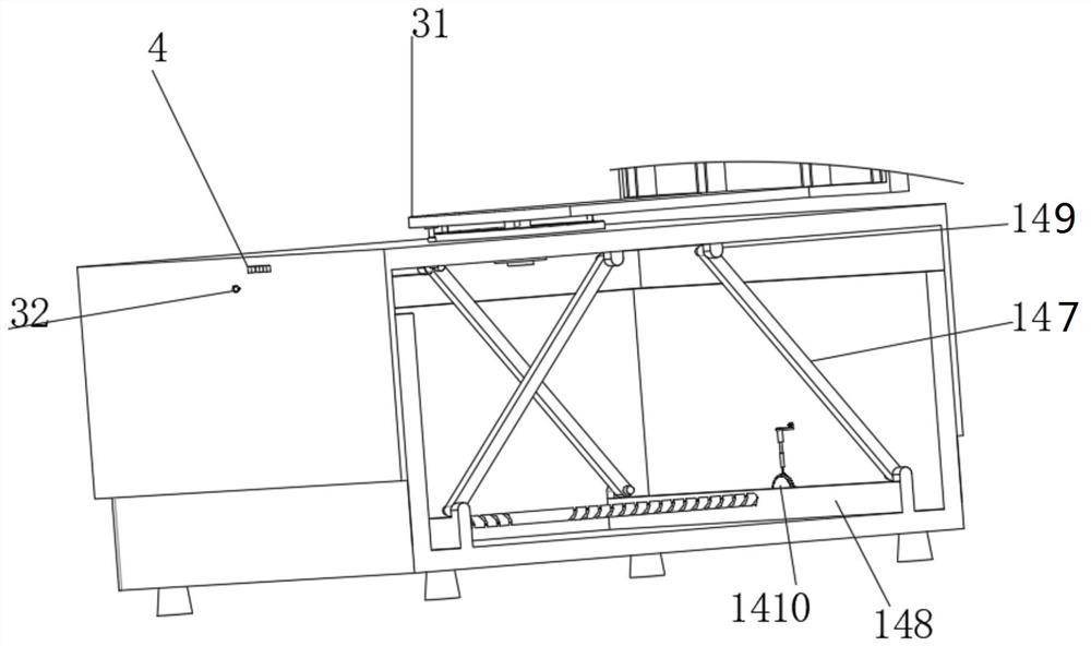
[0041] Such as Figure 1-8The communication equipment maintenance device shown includes a fixed box body 1. The inner bottom of the fixed box body 1 is connected with a height adjustment mechanism 14 for adjusting the height of the communication equipment. The height adjustment mechanism 14 includes a second drive motor 141, The fourth ring gear 142, the second ring gear 143, the second mounting plate 144, the thread groove 145, the second rotating rod 146, the rotating support plate 147, the U-shaped plate 148, the bump 149, the rotating disc 1410, the first right-angle tooth Block 1411, horizontal plate 1412, the second electric push rod 1413, the second spring 1414, the second spring 1415, the square slide bar 1416 and the second right-angle tooth block 1417, the fixed casing 1 inner wall is fixedly connected with the second mounting plate 144 and The horizontal plate 1412, the second mounting plate 144 is fix...


PUM


Abstract

The invention relates to a communication equipment maintenance device in the technical field of communication equipment maintenance. The communication equipment maintenance device comprises a fixed box body; the fixed box body is provided with a height adjusting mechanism; the height adjusting mechanism is provided with a sleeve box; the sleeve box is provided with a switch; the sleeve box is provided with a horizontal rotating structure; the sleeve box is provided with a vertical rotating structure; the vertical rotating structure comprises an n-shaped plate, a first rotating rod, an arc-shaped toothed plate, a U-shaped plate, a first driving motor, a first mounting plate, a first gear ring, a second gear ring, a first electric push rod, an arc-shaped sliding block, a third gear ring, an arc-shaped groove and an arc-shaped rubber plate; the arc-shaped toothed plate is provided with a supporting plate; the supporting plate is provided with an L-shaped supporting plate; the L-shaped supporting plate is provided with a threaded sleeve; the threaded sleeve is provided with a threaded sleeve rod; the threaded sleeve rod is provided with a rotating disk; the rotating disk is provided with a push rod; the threaded sleeve rod is provided with a pressing plate; and the pressing plate and the supporting plate are provided with rubber plates. According to the communication equipment maintenance device, the part, needing to be maintained, of communication equipment can be conveniently rotated to a proper maintenance angle, and actual maintenance is facilitated.

Description

technical field [0001] The invention relates to the technical field of communication equipment maintenance, in particular to a communication equipment maintenance device. Background technique [0002] The English abbreviation of communication equipment is ICD, and the full name is Industrial Communication Device. This column will comprehensively introduce wired communication equipment and wireless communication equipment suitable for industrial control environments. Wired communication equipment mainly introduces solutions for serial communication on industrial sites, professional bus communication, industrial Ethernet communication and conversion equipment between various communication protocols. Wireless communication equipment is mainly wireless AP, wireless network bridge, wireless network card, wireless lightning arrester, antenna and other equipment. The biggest advantage of wired communication equipment is strong anti-interference, high stability, certain confidentia...

Claims


Application Information

Patent Timeline
Patent Type & Authority Applications(China)
IPC IPC(8): B25H1/16B25H1/18B25B11/00
CPCB25H1/16B25H1/18B25B11/00
Inventor 阚鑫鑫汪国付
Owner 六安保识信息技术有限公司
Why Eureka
Try Eureka