
A Crucible Graphite Platform Structure for Casting Single Crystals

A platform structure and crucible technology, applied in the field of casting single crystal, can solve the problem of low yield and achieve the effect of large single crystal yield

Active Publication Date: 2022-05-27
浙江普智能源装备有限公司
View PDF2 Cites 0 Cited by
  • Summary
  • Abstract
  • Description
  • Claims
  • Application Information

AI Technical Summary

Problems solved by technology

However, this method will lead to the production of many polycrystals when growing single crystals, so the yield is low
Because many furnaces cool down quickly around them, a temperature distribution with high temperature in the center and low surroundings is formed, that is, the isothermal surface is concave to the melt; this is why there are still some polycrystals around the cast single crystal, and the yield rate is high. lower reason

Method used


Image

  • A Crucible Graphite Platform Structure for Casting Single Crystals
  • A Crucible Graphite Platform Structure for Casting Single Crystals
  • A Crucible Graphite Platform Structure for Casting Single Crystals

Examples


Embodiment 1

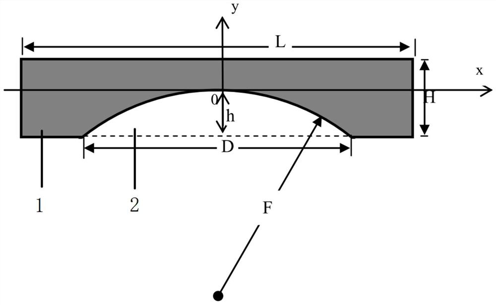
[0029] This Example 1 is directed to a G5 crucible. The side length L of the crucible graphite platform in this Example 1 is 1000 mm, and the thickness H is 120 mm. Take k1=0.618, k2=0.618, and calculate respectively to obtain D = 618mm, h = 74mm, F = 322mm.

[0030] The experimental results of this embodiment 1 are as follows:

[0031] Table 1 The temperature of the top surface of the platform at different distances from the center point at the bottom of the crucible and its change with time (time from the start of crystal growth)

[0032] Crystal growth time (h) 0 4 8 12 16 20 24 28 32 center 1408 1352 1266 1192 1061 960 928 917 880 25cm from the center 1412 1355 1269 1195 1063 962 930 918 881 50cm from the center 1416 1359 1272 1198 1065 963 931 918 881

[0033] It can be seen from Table 1 that when crystal growth starts, the temperature at the bottom of the crucible is 1408 degrees, the temperature at 25 cm...

Embodiment 2

[0035] This Example 2 is directed to G6 crucibles. The side length L of the crucible graphite platform in Example 2 is 1160 mm, and the thickness H is 130 mm. Still take k1=0.618, k2=0.618, and calculate respectively to obtain D = 717mm, h = 80mm, F = 400mm.

[0036] The experimental results of this embodiment 2 are as follows:

[0037] Table 2 The temperature of the top surface of the platform at different distances from the center point at the bottom of the crucible and its change with time (time from the start of crystal growth)

[0038] Crystal growth time (h) 0 4 8 12 16 20 24 28 32 center 1408 1352 1266 1192 1061 960 928 917 880 27cm from the center 1413 1356 1270 1196 1063 962 930 918 881 55cm from the center 1418 1360 1274 1199 1066 965 932 919 882

[0039] It can be seen from Table 2 that when the crystal growth starts, the temperature at the bottom of the crucible is 1408 degrees, the temperature at 2...

Embodiment 3

[0041] This Example 3 is directed to G7 crucibles. The side length L of the crucible graphite platform in Example 3 is 1320 mm, and the thickness H is 140 mm. Still take k1=0.618, k2=0.618. According to the above formula of the present invention, D=816mm, h=87mm, F=481mm can be obtained.

[0042] The experimental results of the present embodiment 3 are as follows:

[0043] Table 3 The temperature of the top surface of the platform at different distances from the center point at the bottom of the crucible and its change with time (time from the start of crystal growth)

[0044] Crystal growth time (h) 0 4 8 12 16 20 24 28 32 center 1408 1352 1266 1192 1061 960 928 917 880 30cm from the center 1414 1357 1271 1196 1063 962 930 917 880 65cm from the center 1420 1362 1275 1200 1066 964 931 918 879

[0045] It can be seen from Table 3 that when crystal growth started, the temperature at the bottom of the crucible wa...


PUM


Abstract

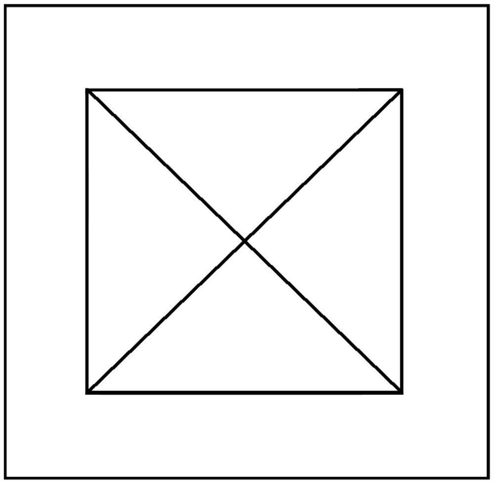
The invention discloses a crucible graphite platform structure for casting single crystal. The outer contour shape of the graphite crucible platform is a flat cube. There is a concave structure in the middle of the bottom of the graphite crucible platform. The edge shape of the bottom opening of the concave structure is square, and the center of the bottom opening of the concave structure coincides with the center of the bottom surface of the graphite crucible platform. , there is a distance between the four sides of the bottom opening of the concave structure and the four sides of the bottom surface of the crucible graphite platform, and the concave structure is a curved surface formed by the intersection of two parabolic cylinders. The beneficial effect of the present invention is that it can effectively ensure that the seed crystal at the bottom of the crucible can keep the state of melting at the top while not melting at the bottom when casting a single crystal, and ensure that the solid-liquid interface is always on a plane during the growth of the single crystal. Gradually rise, so that the single crystal on each seed crystal keeps vertical growth when casting single crystal, so as to achieve the maximum single crystal rate.

Description

technical field [0001] The invention relates to the technical field of casting single crystals, in particular to a crucible graphite platform structure for casting single crystals. Background technique [0002] The traditional single crystal silicon is drawn by the CZ method, and the single crystal growth process is carried out by a directional solidification method similar to the polycrystalline silicon ingot, which is also called cast single crystal or ingot single crystal, because the cost of casting single crystal is Compared with the CZ method, the process cost of single crystal can be greatly reduced, which has attracted the interest of many research institutions and manufacturers. The traditional ingot single crystal is to spread the single crystal seed crystal on the bottom of the square quartz ceramic crucible first, then put the polycrystalline silicon material on the seed crystal, put it into the casting single crystal furnace to melt the polycrystalline silicon m...

Claims


Application Information

Patent Timeline
Patent Type & Authority Patents(China)
IPC IPC(8): C30B29/06C30B15/10
CPCC30B29/06C30B15/10
Inventor 史珺
Owner 浙江普智能源装备有限公司
Learn More