Grafting knife for small plants

A grafting knife and plant technology, which is applied in the field of grafting of small plants, can solve problems such as injury, inconvenient wrapping, and reduced compactness between the epidermis and branches, and achieve the effect of high survival rate and fast grafting speed

Pending Publication Date: 2021-10-01
玉溪紫玉花卉产业有限公司 +1
View PDF0 Cites 1 Cited by
  • Summary
  • Abstract
  • Description
  • Claims
  • Application Information

AI Technical Summary

Problems solved by technology

[0004] At present, in the grafting process of small plants such as roses, it is generally used to cut vertically with a blade, as shown in Figure 1. The small square in the figure is the blade, and then the skin on both sides of the scratch is peeled off to both sides. , and then insert the scion into the epidermis and wrap it up. If the blade is not well grasped, it may cause damage. At the same time, when peeling off the epidermis on both sides, pulling the epidermis outward will reduce the tightness between the epidermis and the branches, and the later wrapping will not convenient

Method used


Image

  • Grafting knife for small plants
  • Grafting knife for small plants
  • Grafting knife for small plants

Examples


Embodiment 1

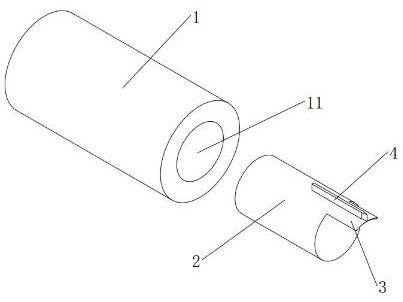
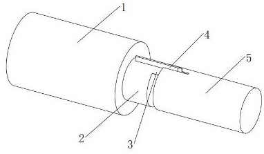
[0018] Such as figure 2 As shown, a grafting knife for small plants includes a handle 1, a connecting cylinder 2, a main blade 3 and an auxiliary blade 4, the main blade 3 can be processed from the connecting cylinder and formed integrally, and one end of the handle 1 is provided with A round hole 11, one end of the connecting cylinder 2 is inserted into the round hole 11, and the other end is left outside the round hole 11, the main blade 3 is located at the outer end of the connecting cylinder 2, and the main blade 3 extends outward along the outer edge of the connecting cylinder 2, The main blade 3 is arc-shaped and is consistent with the arc of the connecting cylinder 2; the secondary blade 4 is vertically placed on the outer wall of the main blade 3, and the blades of the main blade 3 and the secondary blade 4 are located at the outermost end (i.e. figure 2 center right).

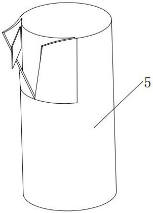
[0019] Such as image 3 As shown, the plant 5 is first cut flat with scissors, and then the end...

Embodiment 2

[0037] Such as Figure 4 As shown, the specific implementation method is the same as that of Example 1, the difference is that: the opposite end of the auxiliary blade 4 is provided with a flat block 41, and the connecting cylinder 2 corresponding to the block 41 is provided with a flat groove 21; An arc-shaped groove-shaped buckle 44 is provided on the outside of the locking block 41 of the auxiliary blade 4 , and a cylinder matching the buckle 44 is arranged in the flat groove 21 . When installing, the sub-blade can be inserted at a slightly inclined angle (the size in the picture is for the convenience of display, not the actual real size, there is no problem during installation), the buckle is restricted by the cylinder, and then the opposite side of the buckle is forced into the flat concave The groove is fixed to prevent the sub-blade from falling out, so that the positioning of the sub-blade is more accurate and the card position is more in place. After the block of th...


PUM


Abstract

The invention relates to grafting of small plants such as roses, in particular to a grafting knife for small plants, and aims to solve the problem of plant grafting. The grafting knife for small plants comprises a grab handle, a connecting column, a main blade and an auxiliary blade, a round hole is formed in one end of the grab handle, one end of the connecting column is inserted into the round hole, the other end of the connecting column is reserved outside the round hole, the main blade is located at one end of the outer side of the connecting column and extends outwards along the edge of the outer side of the connecting column, and the main blade is arc-shaped and consistent with the connecting column in radian; and the auxiliary blade is vertically arranged on the outer side wall of the main blade, and cutting edges of the main blade and the auxiliary blade are located at the outermost end. The grafting knife has the advantages of small plant wound surface injury, higher personnel operation safety, ingenious and convenient structure, quickness in disassembly and assembly, low maintenance cost, high grafting speed and high survival rate.

Description

technical field [0001] The invention relates to the grafting of small plants such as roses, in particular to a grafting knife for small plants. Background technique [0002] Grafting is one of the methods of artificial propagation of plants. That is to graft the branch or bud of one plant onto the stem or root of another plant, so that the two parts joined together grow into a complete plant. Grafting methods are divided into branch grafting and bud grafting. Grafting is carried out by utilizing the ability of plants to heal after injury. [0003] Grafting is a type of vegetative reproduction in asexual reproduction. When grafting, the scion should be closely combined with the cambium of the rootstock to ensure the survival of the scion. The connected branches or buds are called scions; the grafted plant bodies are called rootstocks or platform wood. Generally select the seedling of tool 2 to 4 buds during scion, become the upper part or the top of plant body after graf...

Claims


Application Information

Patent Timeline
Patent Type & Authority Applications(China)
IPC IPC(8): A01G2/35
CPCA01G2/35
Inventor 张军云段家彬钱遵姚杨光炤张建康王文智刘庆荣张钟段梦涵郭春平杨世先张艳华郭凤鸣牟子蛟卢玉娥王春华
Owner 玉溪紫玉花卉产业有限公司
Why Eureka
Try Eureka