Horizontal shaft tidal current energy water turbine and using method
A water turbine and tidal current energy technology, which is applied in mechanical equipment, hydroelectric power generation, ocean energy power generation, etc., can solve the problems of not being able to maximize the efficiency, reduce flow separation and energy loss, increase stall angle of attack, and improve boundary The effect of layer separation
- Summary
- Abstract
- Description
- Claims
- Application Information
AI Technical Summary
Problems solved by technology
Method used
Image

Examples
Embodiment 1
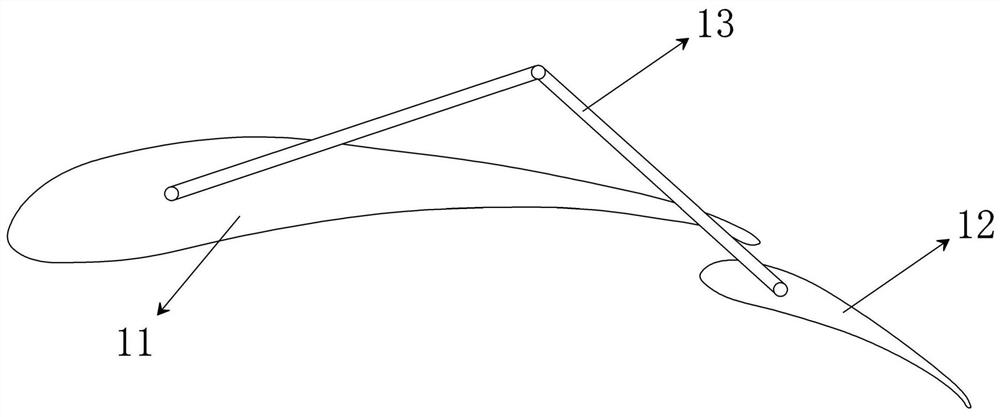
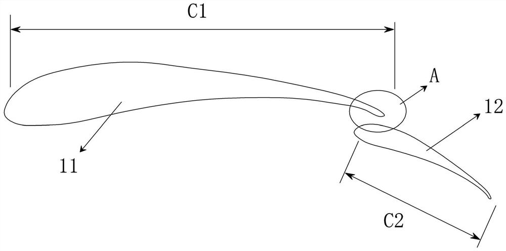
[0036] like Figure 1 to Figure 5 As shown, the present embodiment provides a horizontal axis tidal energy turbine blade 1, including a main wing 11 and a flap 12, wherein the flap 12 is arranged at the trailing edge of the main wing 11, and there is a possible Variable-area permeable channels.
[0037] Further, such as figure 1 As shown, the main wing 11 and the flap 12 are connected by a crank connecting rod 13, wherein one end of the crank connecting rod 13 is installed at the 1 / 3 chord length from the leading edge of the main wing 11 blade tip, and the other end is installed at a distance from the flap 12. 1 / 3 of the chord length of the leading edge of the blade tip; through the crank connecting rod, the flap 12 can be deflected around the trailing edge of the main wing 11 to change the radian of the blade 1 . It should be noted that the connection between the main wing 11 and the flap 12 is not limited to the crank connecting rod 13, but also can be connected through ot...
Embodiment 2
[0041] like Figure 4 to Figure 5 As shown, the present embodiment provides a horizontal axis tidal energy water turbine, including a support structure 4 and a water turbine installed on the top of the support structure 4, wherein the water turbine includes a cabin 3 connected to the support structure 4, a cabin installed inside the cabin 3 The generator (not shown in the figure), the hub 2 connected to the generator shaft and the blades 1 of several embodiments installed on the hub in the circumferential direction, wherein the main wing 11 is fixedly connected to the hub 2, and the flap 12 is installed on the hub 2 On the slideways arranged in the circumferential direction, the crank connecting rod 13 is connected with the driving device (not shown in the figure) arranged in the hub 2; the water turbine is directly fixed on the seabed through the support structure 4.
[0042]When working, the water flow drives the blade 1 to rotate, and then drives the hub 2 connected with th...
Embodiment 3
[0047] Based on the horizontal-axis tidal energy turbine provided in Embodiment 2, this embodiment provides its specific usage method, as follows:
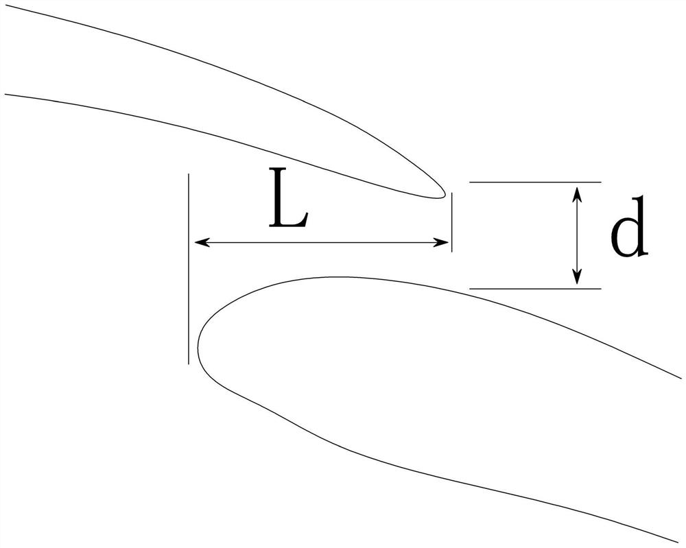
[0048] When the water turbine is in the normal working state, the driving device does not work. At this time, the water flow passes through the water-permeable channel between the main wing 11 and the flap 12, and the water-flow at the trailing edge of the suction surface of the main wing 11 is increased by using the water-permeable channel to inject the fluid. flow rate;
[0049] When the water turbine blade needs to be adjusted, the driving device works, and the driving device controls the crank connecting rod 13 to run, and the crank connecting rod 13 drives the flap 12 to slide along the slideway on the hub 2, so that the overall curvature of the blade 1 increases.
PUM
 Abstract
Description
Claims
Application Information
 - R&D
- Intellectual Property
- Life Sciences
- Materials
- Tech Scout
- Unparalleled Data Quality
- Higher Quality Content
- 60% Fewer Hallucinations
Browse by: Latest US Patents, China's latest patents, Technical Efficacy Thesaurus, Application Domain, Technology Topic, Popular Technical Reports.
© 2025 PatSnap. All rights reserved.Legal|Privacy policy|Modern Slavery Act Transparency Statement|Sitemap|About US| Contact US: help@patsnap.com