
Dynamic mechanical property testing device for amorphous alloy and method thereof

A technology of dynamic mechanics and amorphous alloys, applied in measuring devices, scientific instruments, strength characteristics, etc., can solve difficult problems such as the study of dynamic mechanical properties of amorphous alloys

Active Publication Date: 2021-10-08
BEIJING INSTITUTE OF TECHNOLOGYGY
View PDF12 Cites 0 Cited by
  • Summary
  • Abstract
  • Description
  • Claims
  • Application Information

AI Technical Summary

Problems solved by technology

The above problems make it difficult to apply the Hopkinson experimental technique to the study of the dynamic mechanical properties of amorphous alloys.

Method used


Image

  • Dynamic mechanical property testing device for amorphous alloy and method thereof
  • Dynamic mechanical property testing device for amorphous alloy and method thereof
  • Dynamic mechanical property testing device for amorphous alloy and method thereof

Examples


Embodiment 1

[0081] (1) Preparation of Zr 58 Cu 12 Ni 12 al 15 Nb 3 Amorphous alloy: Zr, Cu, Ni, Al, Nb with purity ≥ 99.99%, 5 kinds of metals are mixed according to the atomic percentage of 58:12:12:15:3, arc melting in a high-purity argon atmosphere, first The Zr-Nb binary alloy is melted, then mixed with other metal elements to melt the master alloy ingot, and then the alloy ingot is melted and poured into a copper mold. The size of the copper mold is Φ5mm*50mm, and the Zr-based amorphous alloy sample is prepared.

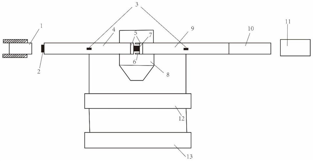
[0082] (2) Process the sample into a cylindrical sample 7 of Φ3mm*3mm, use 400#-2000# sandpaper to grind the upper and lower bottom surfaces of the cylindrical sample from small to large, so that the flatness of the two end faces of sample 7 is better than 5 μm, and then Rinse and dry with absolute ethanol.

[0083] (3) The sample 7 is placed between the incident rod 4 and the transmission rod 9, and a stop ring 6 made of 18Ni300 maraging steel with an outer diameter o...

Embodiment 2

[0088] (1) Preparation of Zr 63 Cu 12 Ni 12 al 10 Nb 3 Amorphous alloy: Zr, Cu, Ni, Al, Nb with a purity ≥ 99.99%, 5 kinds of metals are mixed according to the atomic percentage 63:12:12:10:3, arc melting in a high-purity argon atmosphere, first The Zr-Nb binary alloy is melted, then mixed with other metal elements to melt the master alloy ingot, and then the alloy ingot is melted and poured into a copper mold. The size of the copper mold is Φ5mm*50mm, and the Zr-based amorphous alloy sample is prepared.

[0089] (2) Process the sample into a cylindrical sample 7 of Φ3mm*3mm, use 400#-2000# sandpaper to grind the upper and lower bottom surfaces of the cylindrical sample from small to large, so that the flatness of the two end faces of sample 7 is better than 5 μm, and then Rinse and dry with absolute ethanol.

[0090] (3) The sample 7 is placed between the incident rod 4 and the transmission rod 9, and a stop ring 6 made of 18Ni300 maraging steel with an outer diameter of...


PUM

PropertyMeasurementUnit
Diameteraaaaaaaaaa
Lengthaaaaaaaaaa
Lengthaaaaaaaaaa

Abstract

The invention discloses a dynamic mechanical property testing device for amorphous alloy and a method thereof. The device comprises a loading rod, a buffer device, a sample, a strain gauge, a red copper sheet, a super dynamic strain gauge and a computer data acquisition system, and the loading rod comprises an impact rod, an incident rod, a transmission rod and an absorption rod which are coaxially arranged in sequence. According to the invention, improvement is carried out on the basis of an existing Hopkinson bar experiment, and a waveform shaper (red copper sheet) with a specific size, a cushion block, a limiting ring and a recovery device are added, so that the problems of non-uniform stress, non-constant strain rate deformation, stress wave dispersion, difficulty in recovery and the like caused by high strength and poor plasticity of an amorphous alloy are solved; the strain rate of the amorphous alloy sample to be tested can be changed by changing the diameter and the thickness of the red copper sheet of the shaper, and the dynamic mechanical property of the amorphous alloy under the high strain rate can be accurately obtained.

Description

technical field [0001] The invention relates to the technical field of testing dynamic mechanical properties of materials, in particular to a testing device and method for dynamic mechanical properties of amorphous alloys. Background technique [0002] Amorphous alloys have high strength, high hardness, high fracture toughness, high elastic limit and good energy absorption capacity, and have broad application prospects in the field of impact dynamics. In order to promote the application of amorphous alloys in the field of high-speed impact, it is necessary to study the dynamic mechanical properties of amorphous alloys. [0003] The Hopkinson compression bar technique is an experimental method for studying the dynamic mechanical properties of materials under high strain rates. Due to the high strength and poor plasticity of amorphous alloys, it is difficult to prepare large-sized bulk materials due to the limitation of amorphous forming ability. The amorphous alloy samples a...

Claims


Application Information

Patent Timeline
IPC IPC(8): G01N3/307
CPCG01N3/307G01N2203/0044G01N2203/0075G01N2203/0617G01N2203/0682
Inventor 王扬卫谈燕程兴旺安瑞付强徐子祁
Owner BEIJING INSTITUTE OF TECHNOLOGYGY
Features
  • Generate Ideas
  • Intellectual Property
  • Life Sciences
  • Materials
  • Tech Scout
  • Unparalleled Data Quality
  • Higher Quality Content
  • 60% Fewer Hallucinations
Learn More