Broadband folding back cavity micro-perforated sound absorption structure

A micro-perforation, wide-band technology, applied in the direction of sound-producing instruments, instruments, etc., can solve the problems of affecting the sound absorption effect, high manufacturing cost, complex structure, etc., achieving good adaptability, avoiding interference problems, and small volume.

Pending Publication Date: 2021-10-08
NAVAL UNIV OF ENG PLA
View PDF2 Cites 6 Cited by
  • Summary
  • Abstract
  • Description
  • Claims
  • Application Information

AI Technical Summary

Problems solved by technology

This control method needs to cooperate with multiple pistons and control mechanisms, resulting in complex structure, high manufacturing cost, and complicated operation; (2) Based on the piston can only complete linear operation, the airtight piston of this scheme can only be used in the last Moving up and down in the straight channel, this makes the difference in the equal sound absorption length of each curved FP channel not too large, thus limiting the sound absorption effect in the wide frequency range, especially in the low frequency range
(3) It can be seen from the figure that the cover plate is located on one side of the zigzag FP channel, and the different lengths from the entrance to the exit of the zigzag FP channel correspond to the sound absorption holes on the cover plate, which will cause sound waves to transmit There is a problem of interference in the process, which affects the overall sound absorption effect

Method used


Image

  • Broadband folding back cavity micro-perforated sound absorption structure
  • Broadband folding back cavity micro-perforated sound absorption structure
  • Broadband folding back cavity micro-perforated sound absorption structure

Examples


Embodiment

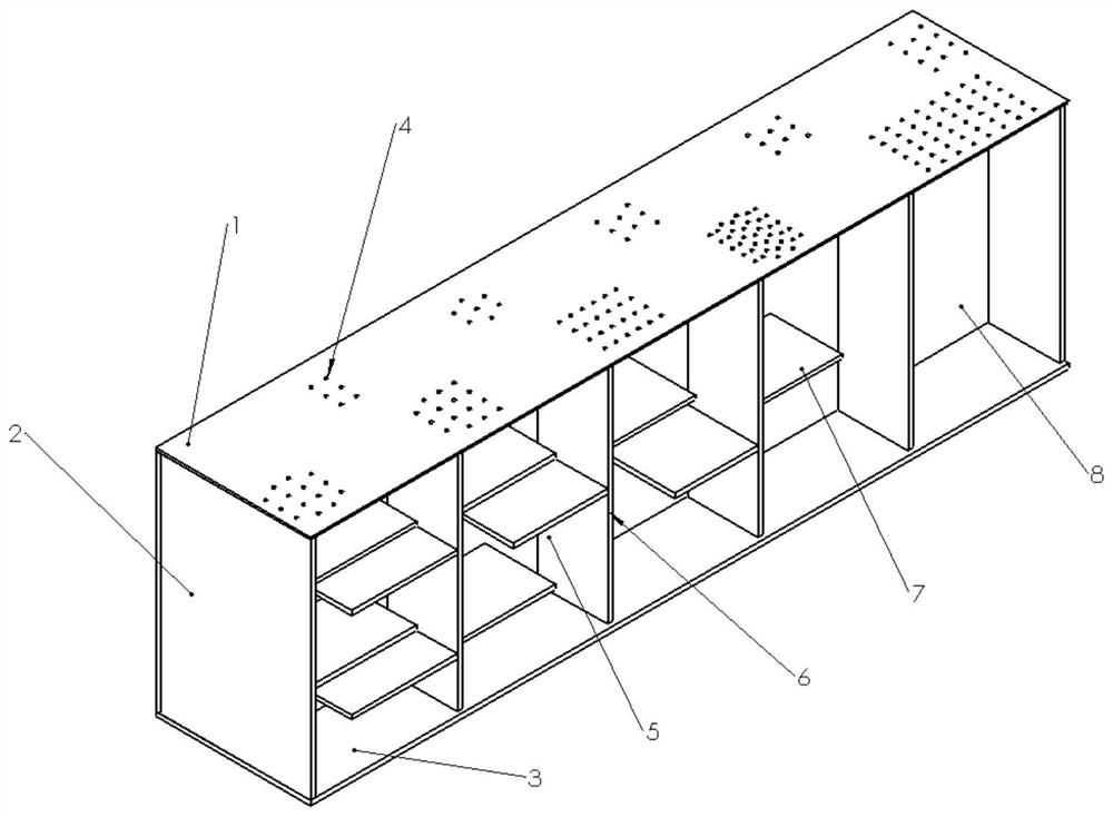
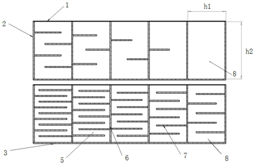
[0027] see figure 2 , the side wall 2, the bottom plate 3, the longitudinal main partition 6 and the transverse sub-partition 7 are all directly printed with the overall back cavity by 3D printing. The thickness of side wall 2, bottom plate 3, longitudinal main partition 6 and transverse sub-partition 7 is 0.6mm, and the length and width of the bottom plate are 100mm*20mm, which are divided into 10 independent small units, and the first row is from left to right 1st floor, 2nd floor, 3rd floor, 4th floor, 5th floor, the second row from left to right is 6th floor, 7th floor, 8th floor, 9th floor, 10th floor, the length and width of the front and rear side panels are 100mm* 30mm, the length and width of the left and right side panels are 20mm*30mm. The thickness dimension of the sound-absorbing back cavity in the direction perpendicular to the bottom plate 3 is the same as that of the side wall in the direction perpendicular to the bottom plate 3, and its value is 30mm. The pa...


PUM


Abstract

The invention discloses a broadband folding back cavity micro-perforated sound absorption structure which solves the problems that an existing sound absorption structure is complex in structure, limited in overall sound absorption frequency band and the like, and adopts the technical scheme that the broadband folding back cavity micro-perforated sound absorption structure comprises a sound absorption back cavity defined by a bottom plate, a cover plate with micro-perforated holes and side plates. The sound absorption back cavity is divided into a plurality of sound absorption units which are not communicated with one another by a plurality of longitudinal main partition plates; and each sound absorption unit is divided into continuous zigzag cavities folded left and right by multiple layers of transverse sub-partition plates which are arranged in an up-down staggered mode, and the micro-perforated holes in the cover plate are located at the inlet ends of the zigzag cavities. The structure is simple, the size is smaller and thinner, the depth of each zigzag cavity can be conveniently controlled, and the ultra-broadband sound absorption effect is achieved.

Description

technical field [0001] The invention relates to the field of noise control, in particular to a wide-band folding back cavity micro-perforated sound-absorbing structure. Background technique [0002] Sound-absorbing structure is one of the important measures in noise control technology. Traditional sound-absorbing structures are mostly porous fiber materials, such as glass wool, rock wool, etc., plus perforated protective panels. Porous fiber materials have the advantages of good sound absorption performance, but they have poor weather resistance, sound absorption performance will fail after being damp, and long-term use of fibers will cause flying, causing secondary pollution and causing harm to human health. Usually the fiber material needs to be replaced after being used for a period of time, and the fiber will also harm the human body during production and processing. Because the resonant sound-absorbing structure has advantages over traditional porous fiber materials i...

Claims


Application Information

Patent Timeline
Patent Type & Authority Applications(China)
IPC IPC(8): G10K11/162
CPCG10K11/162
Inventor 朱海潮侯九霄孟令晗廖金龙
Owner NAVAL UNIV OF ENG PLA
Why Eureka
Try Eureka