Reverse osmosis filter element and water purifier
A technology of water purifier and filter element, which is applied in the direction of reverse osmosis, osmosis/dialysis water/sewage treatment, general water supply saving, etc. problems, achieve the effects of enhanced flushing power, reduced adhesion, and improved filtration rate
- Summary
- Abstract
- Description
- Claims
- Application Information
AI Technical Summary
Problems solved by technology
Method used
Image

Examples
Embodiment Construction
[0024] In order to make the technical means, creative features, goals and effects achieved by the present invention easy to understand, the present invention will be further described below in conjunction with specific embodiments.
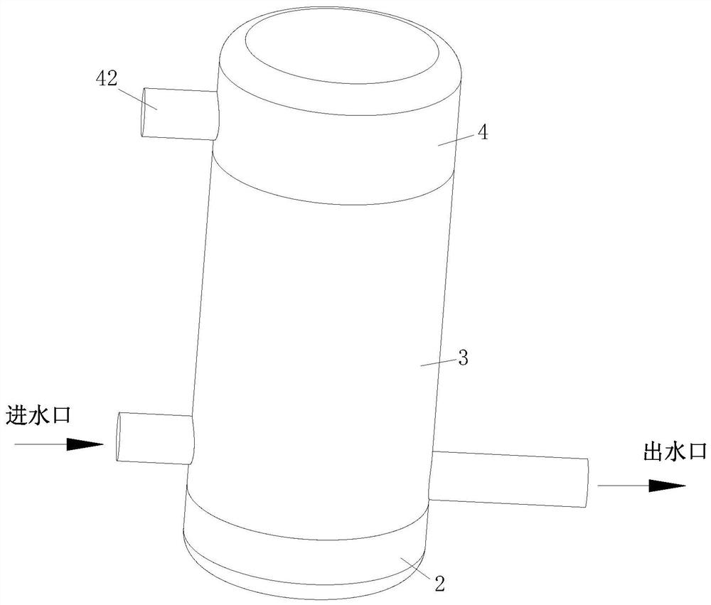
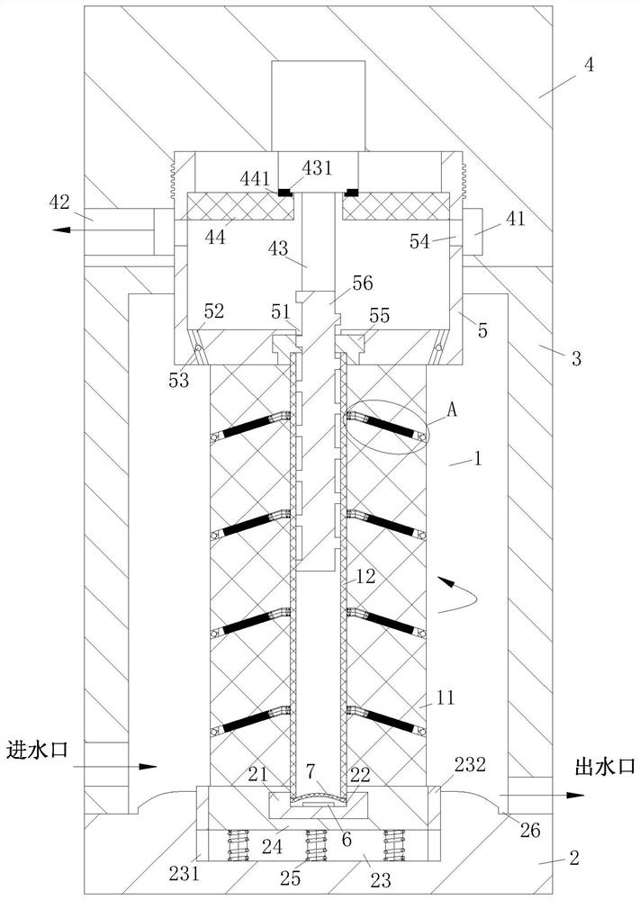
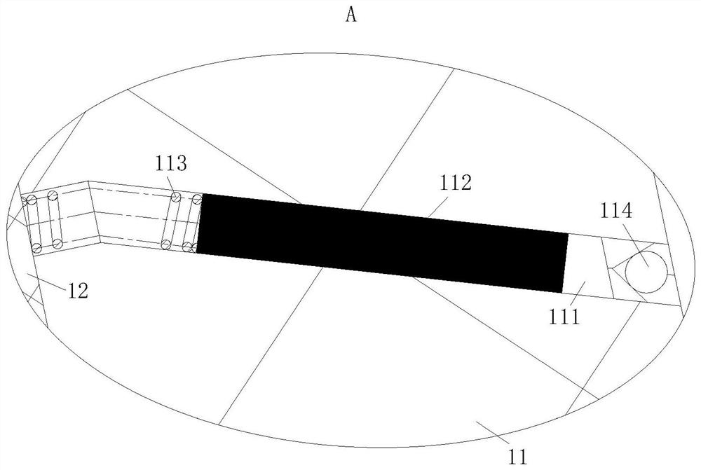
[0025] like Figure 1 to Figure 3 As shown, a kind of water purifier of the present invention comprises filter core 1, filter seat 2, filter cartridge 3, filter cover 4 and controller; The upper end is equipped with a filter element 1; the filter element 1 is located in the filter cartridge 3, and the top of the filter element 1 is provided with a concave block 5, and the filter element 1 includes a filter layer 11 and a guide tube 12; the outer wall of the guide tube 12 is provided with evenly arranged Penetration holes; the concave block 5 is fixedly connected with the filter cartridge 3, and the bottom end of the concave block 5 is provided with a through hole 51; the through hole 51 is located at the center of the bottom end of the concave blo...
PUM
 Abstract
Description
Claims
Application Information
PatSnap Eureka turns technology decisions into work you can execute. Powered by our Innovation Knowledge Graph, it runs expert workflows across engineering, life sciences, materials and intellectual property. Get your review-ready output in minutes.


