Commercial vehicle fuel cell system

A fuel cell system and fuel cell technology, applied in fuel cells, fuel cell additives, fuel cell control, etc., can solve the problems of reducing integration, consuming pipelines, inconvenient overall maintenance, etc., achieving convenient assembly and maintenance, guaranteeing Insulation properties, the effect of improving integration and space utilization

Pending Publication Date: 2021-10-19
重庆明天氢能科技有限公司
View PDF1 Cites 0 Cited by
  • Summary
  • Abstract
  • Description
  • Claims
  • Application Information

AI Technical Summary

Problems solved by technology

The above-mentioned patents have the following deficiencies: the lack of a main frame structure, resulting in the installation of related components in a flat state, which consumes pipelines while reducing the degree of integration, and increases the space occupation, making overall maintenance inconvenient

Method used


Image

  • Commercial vehicle fuel cell system
  • Commercial vehicle fuel cell system
  • Commercial vehicle fuel cell system

Examples


Embodiment 1

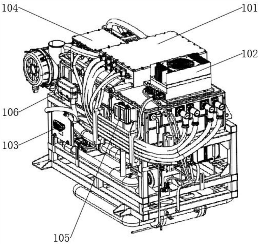
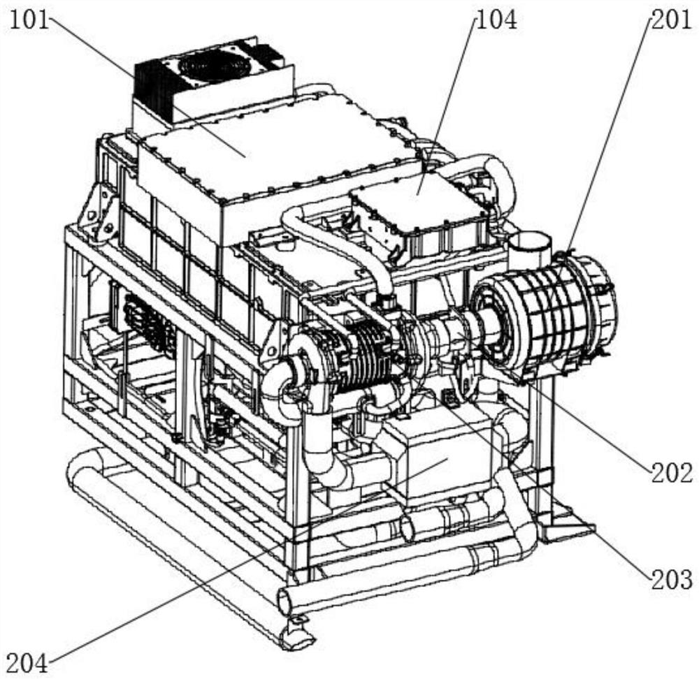
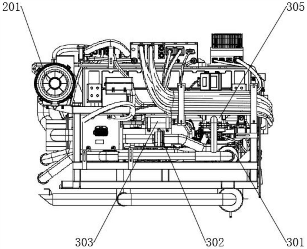
[0035] A commercial vehicle fuel cell system such as Figure 1-8 As shown, it includes an integrated frame and a stack module; the top outer wall of the integrated frame is fixedly connected with a key component mechanism, and the key component mechanism includes an air treatment assembly, a hydrogen processing assembly and a cooling assembly, and the top outer wall of the key component mechanism is fixedly connected with a fuel cell assembly , the top outer wall of the fuel cell assembly is fixedly connected with electrical components, and the partial bottom outer wall of the fuel cell assembly is set on the top outer wall of the integrated frame. The outer wall is provided with a forklift lifting frame; the outer wall of the stack module is provided with the side of the high-voltage plug-in as the first reference plane, the opposite surface of the first reference plane as the second reference plane, and the left-view direction of the first reference plane as the third referen...

Embodiment 2

[0043] A commercial vehicle fuel cell system, including an integrated water separator 403, which is the integrated water separator 403 described in Embodiment 1, and the integrated water separator 403 includes a gas-water separator core 4031, Exhaust solenoid valve 4032 and heated drain solenoid valve 4033, exhaust solenoid valve 4032 and heated drain solenoid valve 4033 are connected to the gas-water separator core 4031 through pipelines, and the outlet end of exhaust solenoid valve 4032 is connected to the hydrogen circulation pump through pipelines 404, one end of the outlet of the heated drain solenoid valve 4033 is connected to the mixer 208 through a pipeline; when in use, the integrated air-water separator 403 is composed of an air-water separator 4031, an exhaust solenoid valve 4032, and a heated drain solenoid valve 4033. On the one hand, it separates hydrogen from water vapor, and the separated hydrogen enters the stack again through the hydrogen circulation pump 404 ...


PUM

PropertyMeasurementUnit
thicknessaaaaaaaaaa

Abstract

The invention discloses a commercial vehicle fuel cell system, and relates to the field of new energy vehicles. The problem that an existing system is low in integration degree and space utilization rate is solved. The system specifically comprises an integrated frame and an electric pile module. The outer wall of the top of the integrated frame is fixedly connected with a key component mechanism. The key component mechanism comprises an air treatment assembly, a hydrogen treatment assembly and a cooling assembly. The outer wall of the top of the key component mechanism is fixedly connected with a fuel cell assembly, and the top outer wall of the fuel cell assembly is fixedly connected with an electrical assembly. According to the fuel cell system, as a main framework of the system, the integrated frame is arranged and can achieve a supporting effect and fix the whole fuel cell system, and related elements can be fixed and disassembled in a detachable mode, so that assembly and maintenance of the system are greatly facilitated; and related parts can be arranged around the integrated frame, so that the integration level and the space utilization rate are improved.

Description

technical field [0001] The invention relates to the field of new energy vehicles, in particular to a commercial vehicle fuel cell system. Background technique [0002] The fuel cell system is usually applied as a powertrain, but the system is still composed of multiple scattered components, and the overall integration level is not high. At present, although commercial vehicles are easy to arrange fuel cell systems due to their large space, more and more commercial vehicle OEMs also require high integration, high space utilization, and easy assembly and maintenance for system layout. [0003] After searching, the Chinese patent application number is CN201810042717.0, which discloses a commercial vehicle fuel cell thermal management system, including a controller, a hydrogen fuel cell system, an electronically controlled three-way valve, an electric heater, a radiator, and a frequency conversion fan , replenishment water tank, frequency conversion water pump, deionization dev...

Claims


Application Information

Patent Timeline
Patent Type & Authority Applications(China)
IPC IPC(8): H01M8/2465H01M8/247H01M8/2475H01M8/04H01M8/04007H01M8/04029H01M8/04082H01M8/04089H01M8/04111H01M8/04119H01M8/04223H01M8/04298H01M8/0438H01M8/04746
CPCH01M8/2465H01M8/247H01M8/2475H01M8/04H01M8/04029H01M8/04201H01M8/04097H01M8/04156H01M8/04089H01M8/04298H01M8/04111H01M8/04126H01M8/04753H01M8/04776H01M8/04425H01M8/04037H01M8/04253H01M8/04268H01M2250/20Y02E60/50
Inventor 侯昌辉张帝朱家辉王朝云
Owner 重庆明天氢能科技有限公司
Why Eureka
Try Eureka