Unlock instant, AI-driven research and patent intelligence for your innovation.

Cutting fluid recycling mechanism for metal cutting and grinding processing of numerical control machine tool

A technology of CNC machine tools and recovery mechanism, which is applied in metal processing machinery parts, metal processing equipment, petroleum industry, etc., can solve the problems of low cooling speed of cutting fluid, cumbersome process, blockage of filter mechanism, affecting adsorption efficiency, etc., to simplify cooling recovery The process of reducing the filter pressure, the effect of the rapid cooling process

Inactive Publication Date: 2021-10-22
嘉兴考普诺机械科技有限公司
View PDF0 Cites 0 Cited by
  • Summary
  • Abstract
  • Description
  • Claims
  • Application Information

AI Technical Summary

Problems solved by technology

[0004] In order to overcome the above-mentioned defects of the prior art, an embodiment of the present invention provides a cutting fluid recovery mechanism for metal cutting and grinding of CNC machine tools to solve the problem that the accumulation of metal impurities inside the cutting fluid in the prior art can easily lead to blockage of the filter mechanism and metal fragmentation. Difficult to quickly collect chips after absorption, which affects the adsorption efficiency and the cooling rate of the cutting fluid is low and the process is cumbersome.

Method used


Image

  • Cutting fluid recycling mechanism for metal cutting and grinding processing of numerical control machine tool
  • Cutting fluid recycling mechanism for metal cutting and grinding processing of numerical control machine tool
  • Cutting fluid recycling mechanism for metal cutting and grinding processing of numerical control machine tool

Examples


Embodiment Construction

[0029] In order to make the technical problems, technical solutions and advantages to be solved by the present invention clearer, the following will describe in detail with reference to the drawings and specific embodiments.

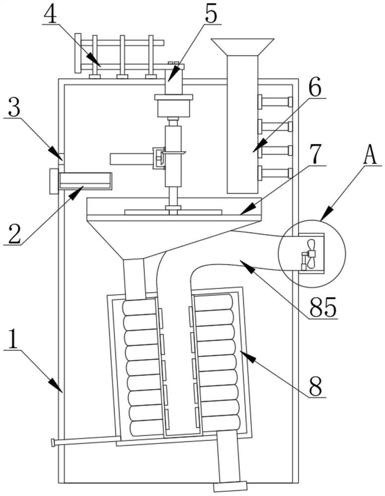
[0030] as attached figure 1 to attach Figure 7 Embodiments of the present invention provide a cutting fluid recovery mechanism for metal cutting and grinding of CNC machine tools, including a recovery box 1, a cutting fluid inlet pipe 6 is fixedly installed on the inner side of the recovery box 1, and the level of the top surface of the cutting fluid inlet pipe 6 is The height is higher than the level of the top surface of the recovery box 1, and the inside of the recovery box 1 is slidably connected with the iron filings storage box 2, and the top surface of the recovery box 1 is fixedly installed with a sliding mechanism 4, and the inner cavity of the recovery box 1 slides An iron chip recovery mechanism 5 is installed, and a filter assembly 7 is fix...


PUM


Abstract

The invention discloses a cutting fluid recycling mechanism for metal cutting and grinding processing of a numerical control machine tool, and particularly relates to the field of numerical control machine tools. The cutting fluid recycling mechanism comprises a recycling box body, a cutting fluid inlet pipe is fixedly mounted on the inner side of the recycling box body, and the horizontal height of the top face of the cutting fluid inlet pipe is larger than that of the top face of the recycling box body; and a scrap iron storage box is slidably connected to the inner side of the recycling box body, a sliding mechanism is fixedly mounted on the top face of the recycling box body, a scrap iron recycling mechanism is slidably mounted in an inner cavity of the recycling box body, and a filtering assembly is fixedly mounted in the inner cavity of the recycling box body. According to the scheme, through the independent action of the scrap iron recycling mechanism, scrap iron and other impurities can be preliminarily separated through rotation of the scrap iron recycling mechanism on the inner side of the filtering assembly in the cutting fluid recycling process, and then the scrap iron is subjected to adsorption treatment through an electromagnetic adsorption assembly; and the function of independently recycling the scrap iron in impurities obtained after cutting fluid is filtered is achieved, the separation effect is improved, and the filtering pressure of a filter screen is reduced.

Description

technical field [0001] The invention relates to the technical field of numerical control machine tools, and more specifically, the invention relates to a cutting fluid recovery mechanism for metal cutting and grinding of numerical control machine tools. Background technique [0002] CNC machine tools solve complex, precise, small-batch, and multi-variety parts processing problems. It is a flexible, high-efficiency automatic machine tool that represents the development direction of modern machine tool control technology. It is a typical mechanical and electrical integration. For chemical products, during the processing of CNC machine tools, it is necessary to use cutting fluid to wash the cutting part, especially for columnar metal products. During the cutting process, the friction between the tool and the plate will generate a lot of heat, which will easily affect the plate. Therefore, in the working process of CNC machine tools, the use of cutting fluid is essential. In ord...

Claims


Application Information

Patent Timeline
Patent Type & Authority Applications(China)
IPC IPC(8): C10M175/00B23Q11/00B23Q11/10C10N40/22
CPCC10M175/0058C10M175/0066B23Q11/1069B23Q11/00C10N2040/22
Inventor 陈波平
Owner 嘉兴考普诺机械科技有限公司