
Power device drain-source parasitic capacitance sub-circuit model and modeling method thereof

A technology for power devices and circuit models, applied in instruments, electrical digital data processing, calculations, etc., can solve problems such as large errors in drain-source capacitance modeling, modeling errors in drain-source capacitances, and inability to meet industry standards, to ensure accurate performance and reliability, increased precision, and increased flexibility

Active Publication Date: 2021-10-22
EAST CHINA NORMAL UNIV +1
View PDF6 Cites 0 Cited by
  • Summary
  • Abstract
  • Description
  • Claims
  • Application Information

AI Technical Summary

Problems solved by technology

[0003] For power devices such as SGT MOSFETs, because there is a shield gate (Shield) in the Trench that is short-circuited to the source in the structure, the particularity of the structure causes two obvious slope changes in the drain-source capacitance as the drain-source voltage changes, resulting in There is a large error in the modeling of the drain-source capacitance
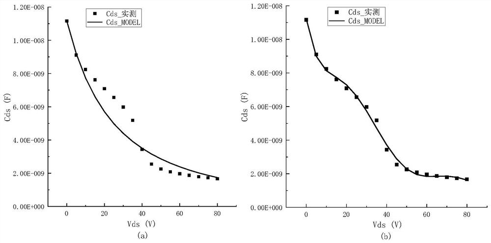
In the current commonly used model, the drain-source capacitance is simulated by a diode added at both ends of the drain-source. Using diode junction capacitance to model the drain-source capacitance will cause relatively large errors, which cannot meet industry standards. Simulation makes an impact

Method used


Image

  • Power device drain-source parasitic capacitance sub-circuit model and modeling method thereof
  • Power device drain-source parasitic capacitance sub-circuit model and modeling method thereof
  • Power device drain-source parasitic capacitance sub-circuit model and modeling method thereof

Examples


Embodiment

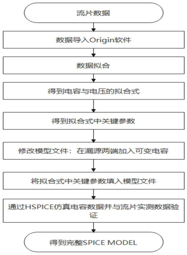
[0022] refer to figure 1 , the modeling process in this embodiment specifically includes:

[0023] 1. Data processing

[0024] Capacitance voltage data processing of tape-out: first, based on the actual test data of the drain-source capacitance voltage of the tape-out device, and import the actual test capacitance voltage data into the Origin software; then process the data in the Origin software, and use the fitting function to establish a drain The source voltage is the independent variable and the drain-source capacitance is the dependent variable sixth-order polynomial fitting formula, such as expression (1), and finally the key coefficients in the fitting formula are obtained, such as A and B in the expression (1) 1 , B 2 , B 3 , B 4 , B 5 , B 6 ;

[0025] Cds=A+B 1 *Vds+B 2 *Vds 2 +B 3 *Vds 3 +B 4 *Vds 4 +B 5 *Vds 5 +B 6 *Vds 6 (1)

[0026] In the formula, Vds is the drain-source voltage;

[0027] 2. Create a model file

[0028] In the model file fo...


PUM


Abstract

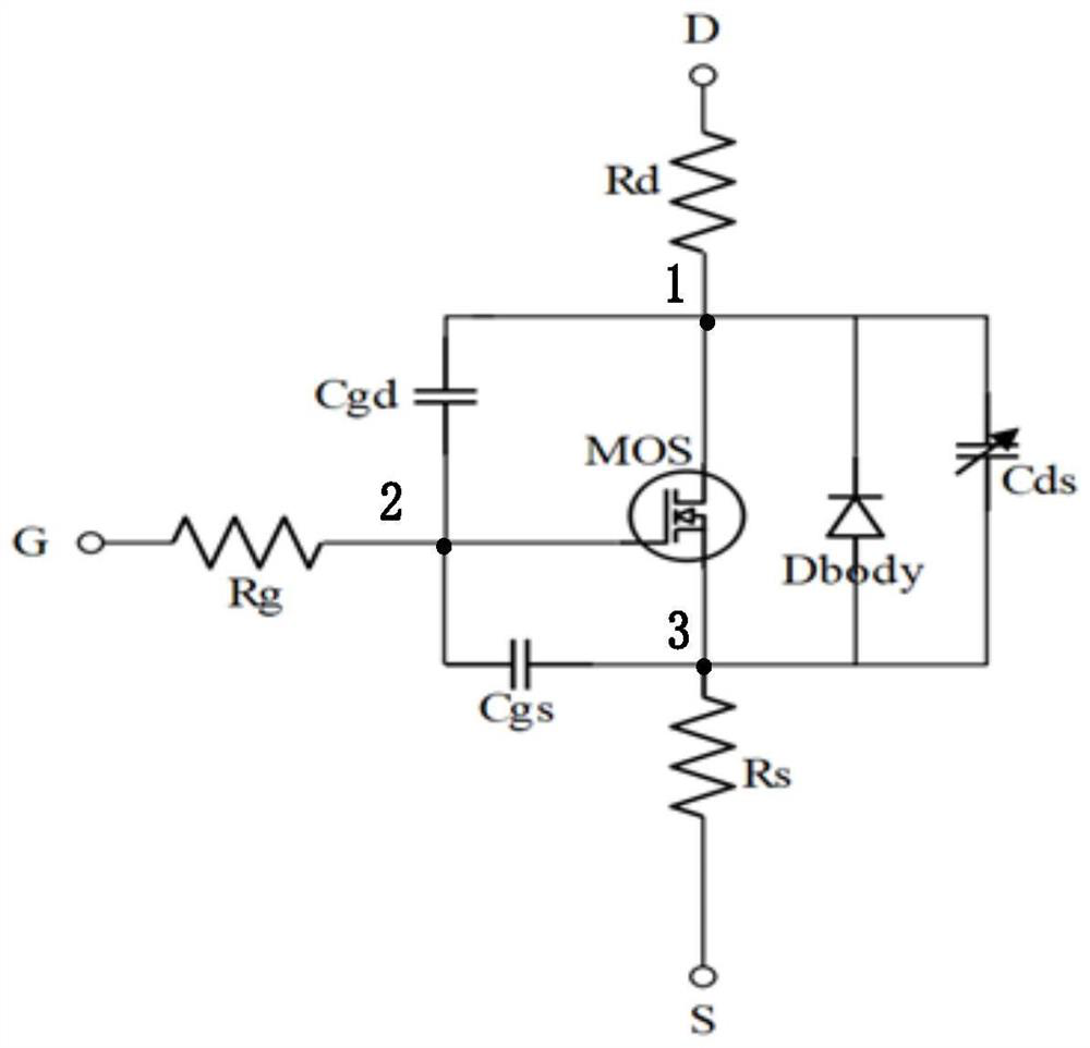
The invention discloses a power device drain-source parasitic capacitance sub-circuit model and a modeling method thereof, and in the power device drain-source parasitic capacitance sub-circuit model, a drain-source capacitor Cds is modeled by adopting a method of adding a variable capacitor between a drain end node and a source end node. The method comprises the following steps: firstly, processing data by utilizing Origin data processing software in combination with actually measured data of drain-source capacitor voltage of the tape-out device; analyzing and establishing a fitting formula of capacitance and voltage in Origin to obtain a corresponding coefficient; inputting corresponding fitting formula coefficient data in the model file according to a format to obtain a complete model; finally, adopting an HSPICE simulator to simulate the result that the drain-source capacitance changes along with the drain-source voltage, wherein the result shows that compared with a conventional method for modeling the drain-source capacitance of a power device through a diode junction capacitor, modeling of the drain-source capacitance through the method is more flexible and accurate.

Description

technical field [0001] The invention belongs to the field of modeling and simulation of power devices, and in particular relates to a power device drain-source parasitic capacitance sub-circuit model and a modeling method thereof. Background technique [0002] The performance simulation of the circuit is carried out on the basis of the device model, and the accuracy of the simulation result mainly depends on the accuracy of the device model. Therefore, the device model is also regarded as a bridge between process production and circuit design, which is a very critical link. At present, the method of modeling power devices at home and abroad is generally the method of the equivalent circuit macro model (Macro Model), that is, the equivalent circuit model of complex devices or new electronic devices is represented by combining the basic device physical models in the SPICE general library. . It is the most convenient and efficient method to model power devices such as SGT MOS...

Claims


Application Information

Patent Timeline
Patent Type & Authority Applications(China)
IPC IPC(8): G06F30/367
CPCG06F30/367
Inventor 孙亚宾谢沛东刘赟石艳玲李小进顾昀浦刘静
Owner EAST CHINA NORMAL UNIV
Learn More