Electronic equipment and antenna device

An antenna device and electronic equipment technology, applied in slot antenna, antenna grounding switch structure connection, circuit and other directions, can solve the problems of increasing the space occupied by the antenna device, increasing the height of the antenna device, etc.

Active Publication Date: 2021-10-22
HUAWEI TECH CO LTD
View PDF16 Cites 1 Cited by
  • Summary
  • Abstract
  • Description
  • Claims
  • Application Information

AI Technical Summary

Problems solved by technology

[0004] However, when the vertical distance between the first antenna radiator of the antenna device and the reference floor is greater than 1 mm, the millimeter-wave antenna device can cover the N257 and N258 dual frequency bands, which makes the antenna device achieve a certain bandwidth. The vertical distance between the first antenna radiator of the antenna device and the reference floor must be increased, that is, the height of the antenna device is increased, which increases the occupied space of the antenna device in the electronic equipment

Method used


Image

  • Electronic equipment and antenna device
  • Electronic equipment and antenna device
  • Electronic equipment and antenna device

Examples


Embodiment 1

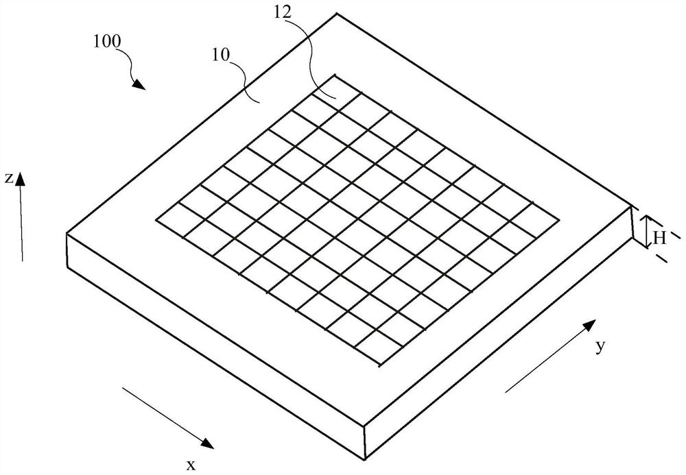
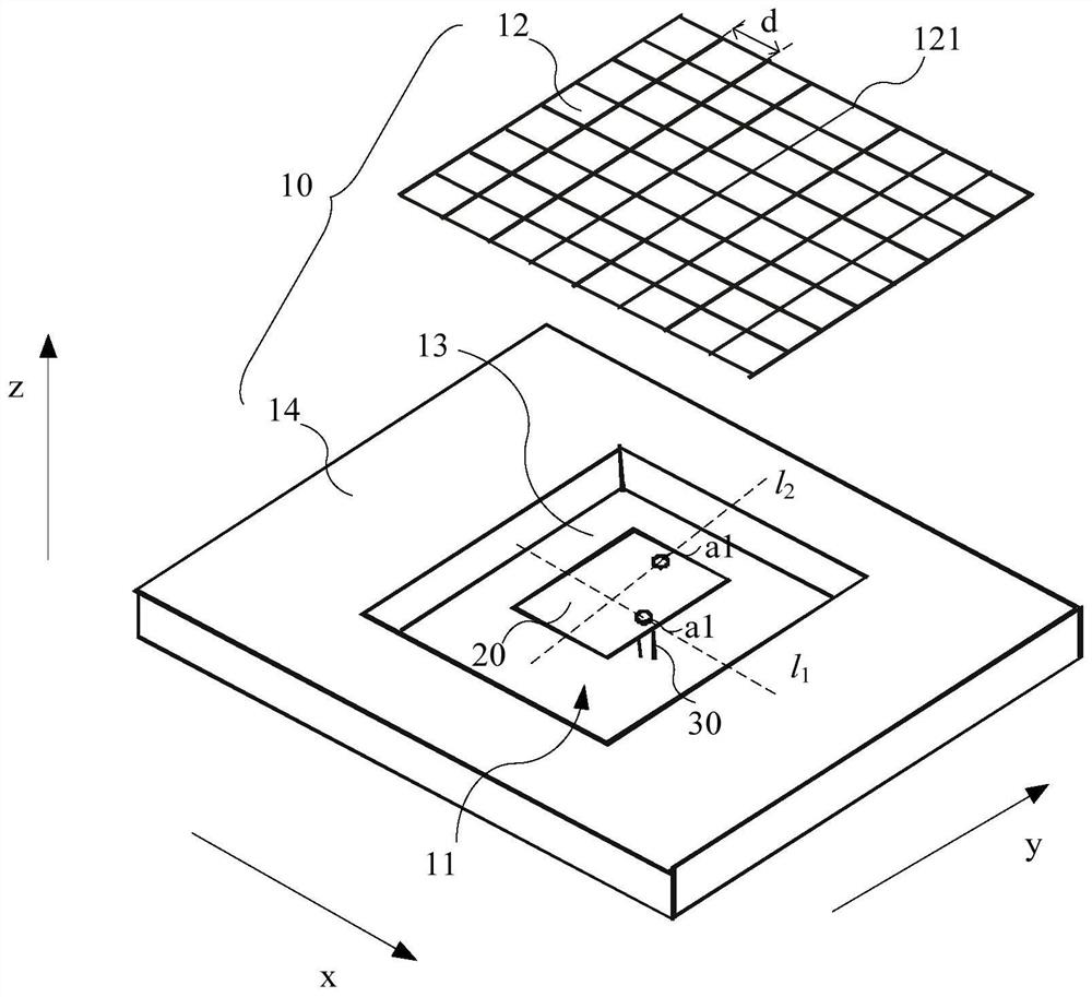
[0073] figure 2 is a schematic diagram of the first structure of the antenna device provided in Embodiment 1 of the present application, image 3 yes image 3 explosion map, Figure 4 yes image 3 A schematic diagram of the internal structure.

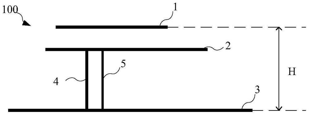
[0074] refer to Figure 2 to Figure 4 As shown, the embodiment of the present application provides an antenna device 100 , including a metal body 10 , a signal transmission source (not shown in the figure), at least one antenna radiator 20 and at least one feeder 30 . Wherein, a hollow cavity 11 is formed in the metal body 10 , each antenna radiator 20 is suspended in the cavity 11 , and the signal emitting source is located outside the metal body 10 .

[0075] Specifically, refer to Figure 4 As shown, the antenna radiator 20 includes a first surface 21 and a second surface 22 opposite to the first surface 21, and the signal transmission source feeds power to the second surface 22 of the antenna radiator 20 through the feed lin...

Embodiment 2

[0126] Figure 12 It is a schematic diagram of the first structure of the antenna device provided in Embodiment 2 of the present application.

[0127] refer to Figure 12 As shown, the difference from Embodiment 1 is that the first end of the feeder 30 connected to the antenna radiator 20 of this embodiment passes through the side wall 14 of the metal body 10 and is connected to the signal emission source, for example, The first end of the first feeder 31 connected to the antenna radiator 20 and the first end of the second feeder 32 pass through the side wall 14 of the metal body 10 and are connected to the signal emission source, so that the feeder 30 is guaranteed to transmit the current to the antenna radiator 20, so that the TM of the antenna radiator 20 and the cavity 11 102 While the modes jointly generate electromagnetic waves with a large bandwidth, the dimension occupied by the feeder 30 in the direction perpendicular to the antenna radiator 20 is reduced, thereby e...


PUM


Abstract

The embodiment of the invention provides electronic equipment and an antenna device. The antenna device comprises a metal main body, a signal emission source, at least one antenna radiator and at least one feeder line, a cavity is formed in the metal main body, each antenna radiator is suspended in the cavity, and the signal emission source is located outside the metal main body; the antenna radiator comprises a first surface and a second surface opposite to the first surface, the signal emission source feeds electricity to the second surface of the antenna radiator through the feeder line, and a plurality of gaps are formed in one surface, opposite to the first surface, of the metal main body, so that electromagnetic waves in the metal main body are emitted to the outside of the metal main body through the gaps. Compared with the prior art, electromagnetic wave energy generated by the cavity of the metal main body can be radiated to a greater extent, so that the radiation bandwidth of the antenna device is increased, and the height size of the antenna device is reduced while a certain radiation bandwidth is ensured.

Description

technical field [0001] The present application relates to the technical field of terminals, and in particular to an electronic device and an antenna device. Background technique [0002] Electronic devices such as mobile phones need to communicate through the mobile communication network provided by the operator, and they can also realize the communication connection between smart devices through wireless fidelity (Wireless Fidelity, WIFI), Bluetooth, infrared and other methods. For mobile phones, communication signals are sent and received through antennas. Because the millimeter-wave frequency band in the 5G spectrum has abundant spectrum resources and high data transmission rate, in the second stage of 5G development, electronic devices such as mobile phones will mainly use millimeter-wave antenna devices to transmit and receive communication signals to improve signal transmission. rate. [0003] In the related art, the millimeter wave antenna device includes a first an...

Claims


Application Information

Patent Timeline
Patent Type & Authority Applications(China)
IPC IPC(8): H01Q13/18H01Q1/36H01Q1/50
CPCH01Q13/18H01Q1/36H01Q1/50
Inventor 邹真林孙树辉珍妮·伊尔沃宁马国忠陈峰文梁娇刘深鹏
Owner HUAWEI TECH CO LTD
Why Eureka
Try Eureka