
A method and device for measuring eye axis based on oct

A measurement method and eye axis technology, which are used in eye testing equipment, medical science, diagnosis, etc., can solve problems such as calculation errors, image plane curvature, and blurred imaging results, and achieve the effect of improving accuracy and eliminating calculation errors.

Active Publication Date: 2022-04-05
ZHEJIANG UNIV +1
View PDF14 Cites 0 Cited by
  • Summary
  • Abstract
  • Description
  • Claims
  • Application Information

AI Technical Summary

Problems solved by technology

However, the existing technology has the following disadvantages: A-ultrasound needs to contact the eyeball, and there are errors caused by sound wave reflection when measuring eye diseases such as cataracts; equipment such as IOL-Master is expensive, and it is difficult to widely use it in domestic hospitals
At present, there are some eye axis measurement methods and devices based on OCT technology. These methods can realize eye axis measurement, but there are still the following disadvantages: In the eye axis measurement systems and methods disclosed in patent documents 202011264580.7, 202010202763. The time-sharing imaging of the eye segment and the posterior segment can measure the axial length of the eye, and the time-sharing imaging may cause the eye axis measurement result to be affected by eye movement; in the eye axis measurement system and method disclosed in patent document 202011037937. Segments can be imaged synchronously, but only the anterior segment is focused, and the posterior segment has only blurred imaging results. The exact imaging position of the posterior segment cannot be determined, which may affect the accuracy of eye axis measurement; disclosed in patent document 201910756738.3 In the ocular axis measurement system and method, the anterior segment and the posterior segment can be imaged synchronously, but the anterior segment light beam is not parallel light at the scanning galvanometer, which may cause a large image plane curvature during imaging, and the diopter in front of the eyepiece is connected to the optical path Limited by the position of the anterior segment optical path, it cannot be adjusted according to the movement of the human eye with different diopters in the actual measurement, which will affect the actual measurement
In particular, the above-mentioned OCT-based eye axis measurement methods have a common deficiency, that is, the calculation formula of the eye axis length includes the inherent optical path of the anterior segment and the posterior segment of the eye in the sample arm. The displacement of the mechanical parts will introduce calculation errors in the measurement of the axial length of the eye

Method used


Image

  • A method and device for measuring eye axis based on oct
  • A method and device for measuring eye axis based on oct

Examples


Embodiment Construction

[0048] Specific embodiments of the present invention will be described in detail below in conjunction with the accompanying drawings, which form a part of this document. It should be noted that these descriptions and examples are illustrative only, and should not be construed as limiting the scope of the present invention. The protection scope of the present invention is defined by the appended claims, and any changes based on the claims of the present invention All are protection scope of the present invention.

[0049] In order to facilitate the understanding of the embodiments of the present invention, each operation is described as a plurality of discrete operations, however, the order of description does not represent the order in which the operations are performed.

[0050] Embodiments of the present invention are as follows:

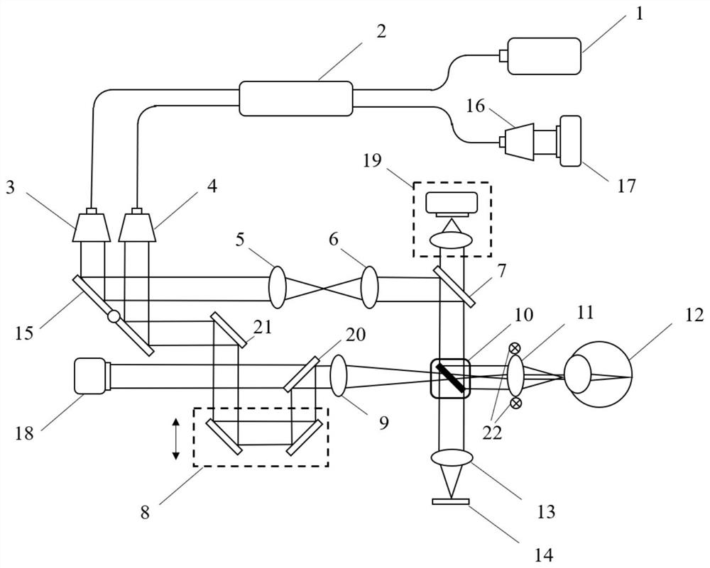
[0051] Such as figure 1 As shown, the eye axis measurement device includes an OCT module, a scanning galvanometer 15, a first fiber collimator ...


PUM


Abstract

The invention discloses an OCT-based eye axis measurement method and device. The method includes: using the reference position calibration method to self-check the optical path of the eye axis measurement, so that the optical path adjustment device of the posterior segment of the eye is at the reference position; adjusting the eye axis measurement device to simultaneously collect the OCT two-dimensional tomography of the cornea and the retina to be measured According to the imaging results, the OCT two-dimensional tomographic imaging results of the cornea and retina of the eye to be tested and the displacement of the optical path adjustment device of the posterior segment of the eye are used to measure the axial length of the eye to be tested. The eye axis measurement device is used for implementing the eye axis measurement method, and realizes the simultaneous OCT two-dimensional tomographic imaging of the anterior segment and the posterior segment of the eye to be measured. The present invention can synchronously focus on the anterior segment and the posterior segment, further realize synchronous and clear imaging of the anterior segment and the posterior segment, and use the reference position calibration method to quickly calibrate the reference position of the optical path of the sample arm before each eye axis measurement , help to improve the accuracy of eye axis measurement.

Description

technical field [0001] The present invention relates to an eye axis measurement method and device belonging to the technical field of medical equipment, in particular to an eye axis measurement method and device based on OCT (Optical Coherence Tomography, optical coherence tomography technology). [0002] technical background [0003] Regular eye examinations are helpful for early diagnosis and treatment of eye diseases. In various ophthalmic examinations, the axial length of the eye can be used to determine the source of the refractive error of the human eye and to measure the parameters of the intraocular lens after cataract surgery. It is an important indicator of ophthalmic examinations. Currently available eye axis measurement methods on the market can be divided into optical coherence biometrics (such as ZEISS IOL-Master, non-contact measurement) and ultrasonic measurement (ie A-ultrasound, contact measurement). However, the existing technology has the following disadv...

Claims


Application Information

Patent Timeline
Patent Type & Authority Patents(China)
IPC IPC(8): A61B3/10A61B3/103A61B3/107
CPCA61B3/102A61B3/103A61B3/107A61B3/0008
Inventor 李鹏张子艺
Owner ZHEJIANG UNIV
Learn More