Welding method of traction transformer copper conductive connection structure

A conductive connection structure, traction transformer technology, applied in the direction of connection, welding medium, welding equipment, etc., can solve the problems of poor conductivity and energy saving effect, poor weld quality, easy to cause air holes, etc., to achieve low production costs and improve Conductive efficiency and the effect of improving flatness

Pending Publication Date: 2021-10-29
SHAANXI SIRUI ADVANCED MATERIALS CO LTD
View PDF0 Cites 1 Cited by
  • Summary
  • Abstract
  • Description
  • Claims
  • Application Information

AI Technical Summary

Problems solved by technology

The existing transformer connection structure has the following technical disadvantages: 1. The structure of the soldered copper conductive connection is mostly single-input and single-output, which occupies a relatively large space, and the conductive efficiency and energy-saving effect are poor; 2. There is a skin effect in induction brazing , for thicker parts, it is easy to bring air holes and poor weld quality

Method used


Image

  • Welding method of traction transformer copper conductive connection structure
  • Welding method of traction transformer copper conductive connection structure
  • Welding method of traction transformer copper conductive connection structure

Examples


Embodiment 1

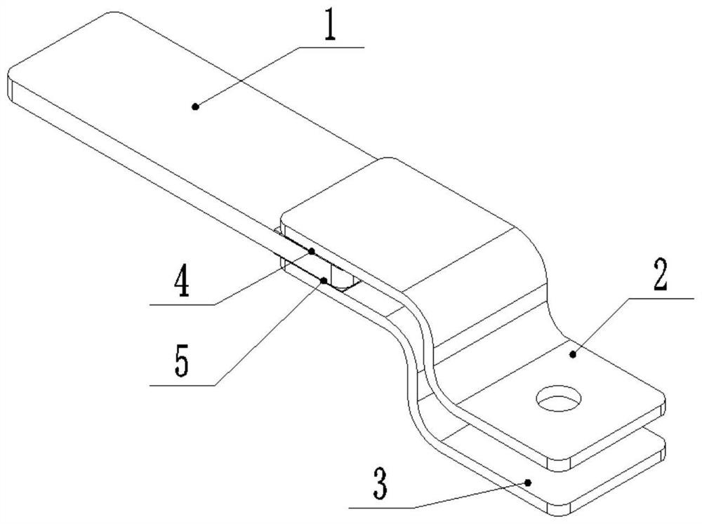
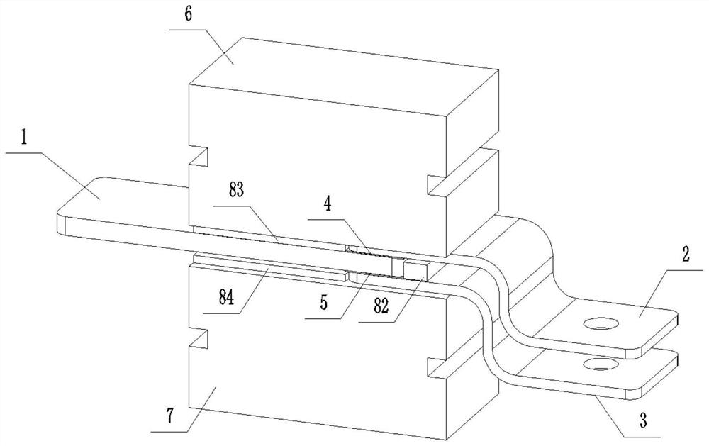
[0031] A welding method for a copper conductive connection structure of a traction transformer. The copper conductive connection structure includes a copper bar 1 and first and second copper foil flexible connectors 2 and 3. The copper bar includes copper and copper alloy rolled plates, drawn rectangular The strip, the flattened bar, the first and second copper foil flexible connectors 2 and 3 are respectively welded to the upper and lower surfaces of one end of the copper bar 1, and the upper and lower surfaces of the other end of the copper bar 1 are provided with graphite electrodes. The two copper foil flexible connectors 2, 3 are connected to the copper bar 1 through the first and second soldering pieces 4, 5 respectively, the first and second copper foil flexible connectors 2, 3 are made of multi-layer copper strips through high Molecular diffusion welding, no solder filling during welding;

[0032] The welding method of the copper conductive connection structure of the ...

Embodiment 2

[0040] This embodiment is basically the same as Embodiment 1, the difference lies in that the pressure range in step S4 is different.

[0041] S4 Fixing the joint: start the power device of the resistance brazing equipment in step S2, press the upper graphite electrode on the welding joint, and ensure that the welding joint is fixed, and the pressure is 10 MPa.

Embodiment 3

[0043] This embodiment is basically the same as Embodiment 1, except that the pressure applied in step S4 is different.

[0044] S4 Fixing the joint: start the power device of the resistance brazing equipment in step S2, press the upper graphite electrode on the welding joint, and ensure that the welding joint is fixed, and the pressure is 20 MPa.


PUM


Abstract

The invention discloses a welding method of a traction transformer copper conductive connecting structure. The conductive connecting structure comprises a copper bar, a first copper foil flexible connecting piece and a second copper foil flexible connecting piece; the first copper foil flexible connecting piece and the second copper foil flexible connecting piece are respectively welded on the upper and lower surfaces of one end of the copper bar, and graphite electrodes are arranged on the upper and lower surfaces of the other end of the copper bar; the first and second copper foil flexible connecting pieces are respectively connected with the copper bar through a first soldering lug and a second soldering lug. The welding method of the traction transformer copper conductive connection structure comprises the following steps: S1, preparing a graphite electrode; S2, installing a graphite electrode; S3, assembling a welding joint; S4, fixing the joint; S5, performing heating and welding; S6, performing cleaning after welding. By adopting the structure that the two copper foil flexible connecting pieces are welded at one end of one copper bar, two flexible output connecting ends can be obtained after one-time welding on one copper bar, so that the manufacturing and production cost of the transformer is lower, the part assembling and mounting efficiency is higher, and the conductive efficiency and the structure optimization are greatly improved.

Description

technical field [0001] The invention relates to the technical field of processing and manufacturing copper conductive connectors for traction locomotive transformers, in particular to a welding method for a copper conductive connection structure of a traction transformer. Background technique [0002] For rail vehicles, the traction transformer is one of the most important equipment, the core part of the entire electric traction system, and the key to ensure the stable operation of most trains, bullet trains, subways, high-speed rail and other track electric locomotives. As the link between the various components in the traction transformer, the copper conductive connector has an important role and significance. [0003] As the voltage level becomes higher and the service environment becomes more and more harsh, the requirements for the optimization of the internal structure of the transformer and the quality standards of the connectors are getting higher and higher. The ex...

Claims


Application Information

Patent Timeline
Patent Type & Authority Applications(China)
IPC IPC(8): H01R43/02B23K1/00B23K35/30B23K35/40
CPCH01R43/0214H01R43/0249H01R43/0263B23K1/0004B23K35/302B23K35/40B23K2101/006B23K2101/36
Inventor 杨帆庾高峰马明月宁超靖林曹延江
Owner SHAANXI SIRUI ADVANCED MATERIALS CO LTD
Why Eureka
Try Eureka