Bidirectional buck-boost converter control method based on reduced-order active-disturbance-rejection strategy
A converter control, active disturbance rejection controller technology, applied in control/regulation systems, output power conversion devices, conversion of DC power input to DC power output, etc. The problem of sudden change in voltage and high complexity can achieve the effect of small overshoot and fluctuation amplitude, improving dynamic response performance and reducing complexity
- Summary
- Abstract
- Description
- Claims
- Application Information
AI Technical Summary
Problems solved by technology
Method used
Image
Examples
Embodiment 1
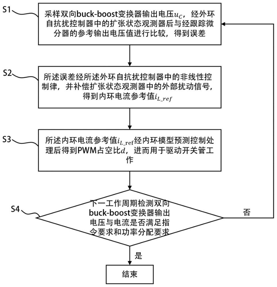
[0066] refer to Figure 1~4 , which is the first embodiment of the present invention, provides a bidirectional buck-boost converter control method based on a reduced-order active disturbance rejection strategy, which includes:
[0067] S1: Sampling the bidirectional buck-boost converter output voltage u C , the error is obtained by comparing the extended state observer in the outer loop ADRC controller with the reference output voltage value of the tracking differentiator;
[0068] S2: The error passes through the nonlinear control law in the outer loop ADRC controller and compensates the external disturbance signal in the extended state observer to obtain the inner loop current reference value i L_ref ;
[0069] S3: Inner loop current reference value After the inner loop model predictive control process, the PWM duty cycle d is obtained, and then used to drive the switch tube to work;
[0070] S4: In the next working cycle, check whether the output voltage and current of...
Embodiment 2
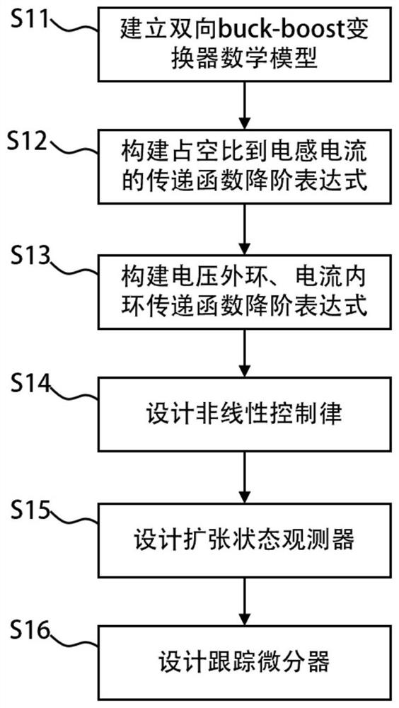
[0085] refer to Figure 2-5 , is the second embodiment of the present invention, and this embodiment is different from the first embodiment in that: the step of establishing the bidirectional buck-boost converter mathematical model also includes: ignoring the secondary and above disturbance items to obtain the bidirectional buck -boost transformer linearization model is
[0086]
[0087] Compared with Embodiment 1, further, the step of S12 constructing the reduced-order expression of the transfer function from the duty cycle to the inductor current includes: performing Laplace transformation on the formula (3), and obtaining the ratio from the duty cycle to the inductor current after finishing. Transfer Function:
[0088]
[0089] The first-order expression is obtained after ignoring its constant term:
[0090]
[0091] The frequency response comparison before and after the order reduction is as follows: Figure 5 shown.
Embodiment 3
[0093] refer to figure 1 and 7 ~10, is the third embodiment of the present invention, and this embodiment is different from the second embodiment in that: S13 constructs the steps of reducing the order expression of the voltage outer loop and current inner loop transfer function as follows: adopt formula (5) Substituting formula (4) as the transfer function from the duty cycle to the inductor current, the transfer function of the voltage outer loop control object and the current inner loop i L_ref to i L The reduced-order expressions of the closed-loop transfer function are:
[0094]
[0095]
[0096] where f s is the control frequency, T s is the control cycle, where the current inner loop control schematic diagram is as follows Figure 6 shown.
[0097] When the inductor current reference value iL _ref When a mutation occurs, i L Can quickly adjust to a given value within about 0.2ms; when the voltage reference value u C_ref (Initial value is set to 250V) When a...
PUM
 Abstract
Description
Claims
Application Information
 - R&D
- Intellectual Property
- Life Sciences
- Materials
- Tech Scout
- Unparalleled Data Quality
- Higher Quality Content
- 60% Fewer Hallucinations
Browse by: Latest US Patents, China's latest patents, Technical Efficacy Thesaurus, Application Domain, Technology Topic, Popular Technical Reports.
© 2025 PatSnap. All rights reserved.Legal|Privacy policy|Modern Slavery Act Transparency Statement|Sitemap|About US| Contact US: help@patsnap.com


