Self-heating assembly and production method

A self-heating and component technology, applied in heating devices, explosives, etc., can solve the problems of high oxygen dependence, high preparation cost, and low safety, and achieve low preparation cost, high heat conduction stability, and increased heating rate Effect

Active Publication Date: 2021-11-02
DALIAN INST OF CHEM PHYSICS CHINESE ACAD OF SCI
View PDF8 Cites 0 Cited by
  • Summary
  • Abstract
  • Description
  • Claims
  • Application Information

AI Technical Summary

Problems solved by technology

[0005] The purpose of this application is to provide a self-heating component and its preparation method, which are used to solve the p

Method used


Image

  • Self-heating assembly and production method
  • Self-heating assembly and production method
  • Self-heating assembly and production method

Examples


preparation example Construction

[0078] According to one aspect of the present application, a method for preparing a self-heating component is provided, such as Figure 5 A flow chart showing a method for preparing a self-heating component according to an exemplary embodiment of the present application, such as Figure 5 It can be seen that the preparation process comprises the following steps:

[0079] In step S510, a fuel material portion is formed at the bottom of the casing;

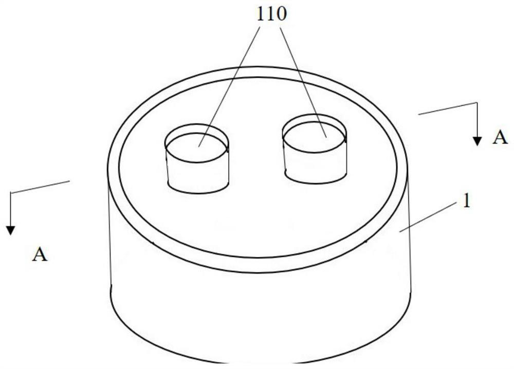
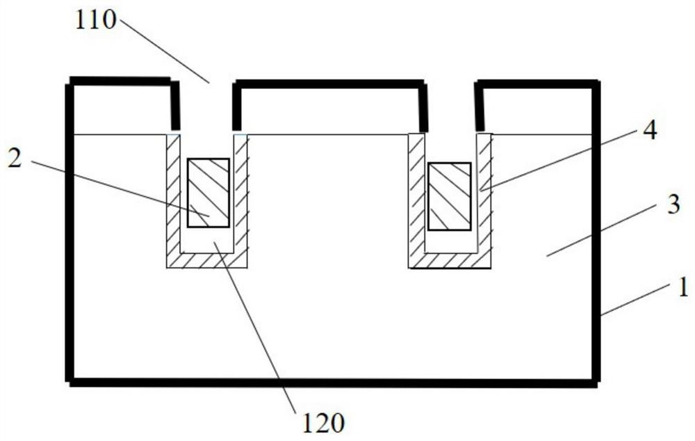
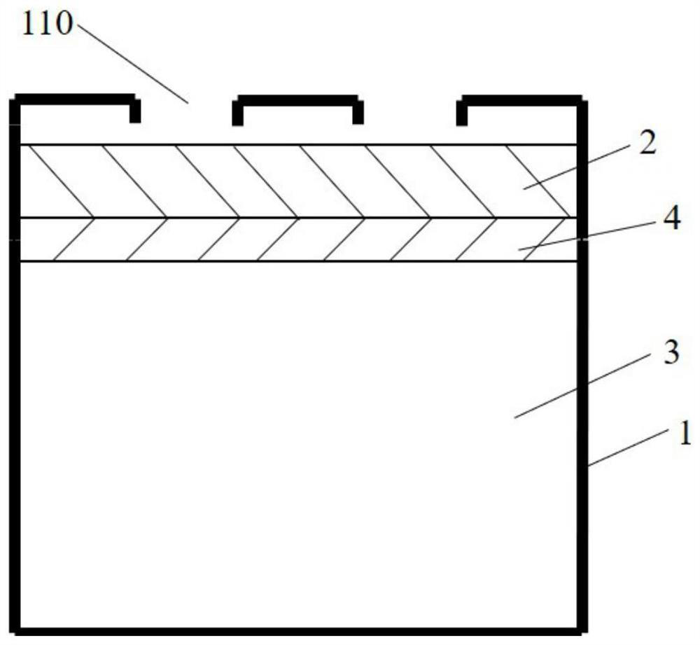
[0080] In this embodiment, the fuel material part can be formed first, and then the fuel material part can be put into the casing; wherein, the fuel material part can be solidified and formed by pouring the pre-molding material of the fuel material part into a pre-customized mold. The application does not specifically limit this. Wherein, the fuel material portion may be provided with grooves with openings facing upwards, and the number of grooves may be, for example, 1, 2, 4, etc., which is not specifically limited in the present...

Embodiment 1

[0091](1) Under normal temperature conditions (20 DEG C), get 10g vegetable oil methyl ester, 30g magnesium powder, 25g calcium peroxide, 5g potassium sorbate and 10g polyurethane glue (this embodiment adopts the room temperature curable polyurethane glue that model is PU-201 Glue), added to a 500ml three-necked round-bottomed flask with stirring and vacuuming functions, and stirred for 5min;

[0092] (2) vacuumize, remove the air bubbles in the three-necked round-bottomed flask, close the stirring device, and make up the pressure in the bottle to normal pressure (0.1MPa) by air;

[0093] (3) Introduce the material in the bottle into a pre-customized mold, place it at room temperature for 30 minutes, realize solidification and molding, and obtain the fuel material part 3 with two upward grooves 120 (see figure 2 shown);

[0094] (4) Prepare the combustible protective layer 4 according to the size of the groove 120;

[0095] (5) According to the size of groove 120, prepare t...

Embodiment 2

[0099] Preparation method of self-heating component

[0100] (1) Under normal temperature conditions (20 ℃), get 10g methyl ester, 20g aluminum powder, 30g calcium peroxide, 2g sodium chloride, 3g potassium sorbate and 35g polyurethane glue (this embodiment adopts the model that can be PU-201 Polyurethane glue cured at room temperature), added to a 500ml three-necked round-bottomed flask with stirring and vacuuming functions, and stirred for 5 minutes;

[0101] Steps (2)~(4) are identical with embodiment 1;

[0102] (5) Prepare two ignition parts 2 according to the size of the groove 120; wherein, after mixing 0.5g of aluminum powder and 1g of potassium dichromate, put them into a single-layer non-woven bag to obtain two ignition parts 2, subsequently placed in the groove 120;

[0103] Steps (6)-(7) are the same as in Example 1.


PUM


Abstract

The invention belongs to the technical field of self-heating equipment, relates to a self-heating assembly and a production method thereof, and aims to solve the problems of a complex packaging structure, high manufacturing process cost, low heating efficiency, a high use risk and the like of the self-heating equipment in related technologies. The self-heating assembly comprises a shell, an ignition mechanism and a fuel material part, wherein the ignition mechanism and the fuel material part are located in the shell. A water inlet is formed in the top of the shell; the ignition mechanism is located under the water inlet hole; and the fuel material part is located at the bottom of the shell and is separated from the ignition mechanism through a combustible protective layer, and the ignition mechanism can generate an exothermic reaction with water. According to the self-heating assembly, after the ignition mechanism reacts with water, generated heat ignites the combustible protective layer, then the fuel material part is ignited to conduct heat outwards, self-heating operation in water is achieved, cost is low, heat conduction is stable, carrying and using are convenient and fast, and the self-heating assembly can be applied to heating scenes with various heat requirements.

Description

technical field [0001] The present application relates to the technical field of self-heating equipment, in particular to a self-heating component and a method for preparing the self-heating component. Background technique [0002] With the progress of the times and the improvement of living standards, people are increasingly pursuing a portable, efficient, safe and hygienic lifestyle. For example, in order to meet the cooking needs of outdoor travel, family picnics, and military field operations, self-heating containers or self-heating fast foods have emerged as the times require. [0003] In related technologies, according to the exothermic process, self-heating containers include physical heating and chemical heating. Among them, physical heating does not generate new substances, but the heat released is very limited, which cannot meet the actual heating needs; and in chemical heating, for example, using The neutralization reaction of acid-base anhydride generates heat. ...

Claims


Application Information

Patent Timeline
IPC IPC(8): A47J36/28C06B33/00C06B33/02
CPCA47J36/28C06B33/00C06B33/02
Inventor 周光远姜敏刘佳王瑞李璐
Owner DALIAN INST OF CHEM PHYSICS CHINESE ACAD OF SCI
Why Eureka
Try Eureka