Manipulator blowing structure and using method thereof

A technology of manipulators and gas parts, applied in the field of manipulators, can solve problems such as poor adsorption, unclean surface of fixtures, affecting processing accuracy and processing efficiency, etc.

Inactive Publication Date: 2021-11-02
成都天码行空机器人研究有限公司
View PDF2 Cites 5 Cited by
  • Summary
  • Abstract
  • Description
  • Claims
  • Application Information

AI Technical Summary

Problems solved by technology

[0007] (1) The traditional blowing rod structure will cause the blowing hole to shift due to the excessive reverse force of the air pressure during blowing. During the blowing process, the clamping degree of the workpiece is easily affected, and the workpiece has the risk of falling
[0008] (2) Most of the traditional air blowing devices have a single-hole single-tube structure, and the air blowing coverage is not large. Often, the surface of the fixture is not clean, which affects the adsorption and fixing effect of the next piece of product, and can only blow air on one part of the workpiece. Cooling will lead to poor adsorption and leakage of grinding, which will affect the processing accuracy and processing efficiency;

Method used


Image

  • Manipulator blowing structure and using method thereof
  • Manipulator blowing structure and using method thereof
  • Manipulator blowing structure and using method thereof

Examples


Embodiment 1

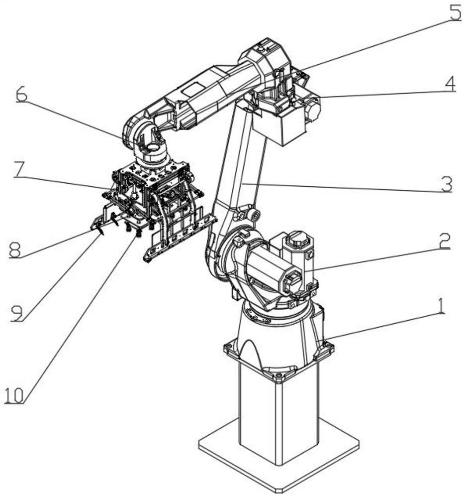
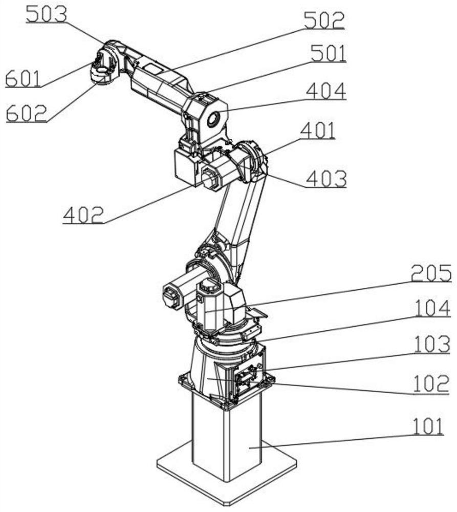
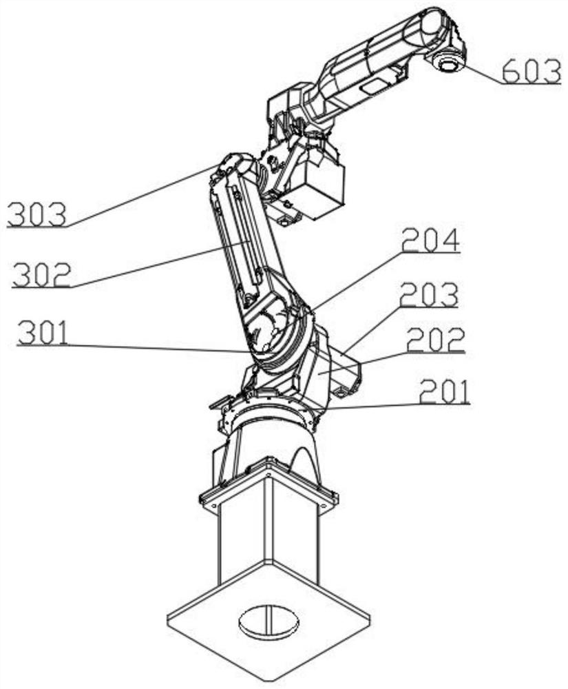
[0057] Such as Figure 1-8 As shown, a blowing structure of a manipulator includes a supporting part, a folding part, a grasping part and an air blowing part. The air blowing part includes an opening and closing assembly 7 and multiple air blowing assemblies 9; multiple air blowing assemblies 9 are symmetrically placed on both sides of the bottom of the opening and closing assembly 7, and the opening and closing assembly 7 drives the air blowing assembly 9 to reciprocate.

[0058] The present invention includes a supporting part, a folding part, a grabbing part and an air blowing part. The supporting part provides supporting force and installation position for the invention. The folding part moves the grabbing part to a suitable grabbing position by folding and opening, and the workpiece After grabbing, the residue and debris of the workpiece are removed by gas blowing through the blowing part, and the workpiece is uniformly cooled. The blowing structure used in traditional eq...

Embodiment 2

[0068] Such as Figure 1-8 As shown, a blowing structure of a manipulator includes a supporting part, a folding part, a grasping part and an air blowing part. The air blowing part includes an opening and closing assembly 7 and multiple air blowing assemblies 9; multiple air blowing assemblies 9 are symmetrically placed on both sides of the bottom of the opening and closing assembly 7, and the opening and closing assembly 7 drives the air blowing assembly 9 to reciprocate.

[0069] The present invention includes a supporting part, a folding part, a grabbing part and an air blowing part. The supporting part provides supporting force and installation position for the invention. The folding part moves the grabbing part to a suitable grabbing position by folding and opening, and the workpiece After grabbing, the residue and debris of the workpiece are removed by gas blowing through the blowing part, and the workpiece is uniformly cooled. The blowing structure used in traditional eq...


PUM


Abstract

The invention relates to the technical field of manipulators, in particular to a manipulator blowing structure. The structure comprises a supporting part, a folding part, a grabbing part and a blowing part, the folding part is rotationally connected with the top of the supporting part, the grabbing part is installed at the top of the folding part, the blowing part is arranged on the grabbing part, and the blowing part comprises an opening and closing assembly and a plurality of blowing assemblies; and the multiple blowing assemblies are symmetrically arranged at the two sides of the bottom of the opening and closing assembly, and the opening and closing assembly drives the blowing assemblies to do reciprocating motion. The invention further provides a using method of the manipulator blowing structure, and the problems that a traditional device blows at a fixed point, the blowing coverage area is not large, the phenomenon that the surface of a clamp is not clean frequently occurs, the adsorption and fixing effect of a next product is affected, the cleaning and cooling effects are poor, the grabbing firmness is reduced, miss grinding occurs, and the machining precision and the machining efficiency are influenced are solved.

Description

technical field [0001] The invention relates to the technical field of manipulators, in particular to a manipulator blowing structure and a method for using the same. Background technique [0002] Joint robot is one of the most common forms of industrial robots in today's industrial field. It is suitable for mechanical automation operations in many industrial fields, such as: automatic assembly, painting, handling, welding and other work. [0003] After the glass products are processed by the CNC machine tool, it is necessary to clean the residue and cutting fluid remaining on the surface of the fixture. The traditional CNC machine tool uses a blowing rod structure fixed on the worktable. This structure is connected to the external compressed air controlled by the solenoid valve in the fixture. Blow air from the side to clean, so as to ensure the adsorption and fixing effect of the fixture, and then repeat the action to process the next product. [0004] The invention with ...

Claims


Application Information

Patent Timeline
Patent Type & Authority Applications(China)
IPC IPC(8): B25J9/00B25J9/04B25J9/14B25J15/06B08B5/02
CPCB25J9/00B25J9/04B25J9/144B25J15/0616B08B5/02
Inventor 李文美
Owner 成都天码行空机器人研究有限公司
Why Eureka
Try Eureka