A self-cleaning exhaust gas waste heat recovery device

A waste heat recovery device and self-cleaning technology, which is applied in the direction of cleaning heat transfer devices, heat exchangers, indirect heat exchangers, etc., can solve problems that affect the effect of waste heat recovery, waste heat is not used, and the device structure is complicated, etc., to achieve the cleaning process Thoroughly solve the waste heat waste and the effect of simple heat exchange structure

Active Publication Date: 2022-03-25
河北和和能源科技有限公司 +1
View PDF0 Cites 0 Cited by
  • Summary
  • Abstract
  • Description
  • Claims
  • Application Information

AI Technical Summary

Problems solved by technology

[0002] A large amount of waste gas will be generated in the process of industrial production. If it is directly discharged to the atmosphere after being treated by purification equipment, although the impact on air pollution is reduced, the waste heat is not utilized, resulting in a large amount of energy waste.
[0003] At present, there are devices on the market that recover waste heat from exhaust gas, but most waste heat recovery devices are mainly for fresh air recovery, and the higher the recovery efficiency, the more complicated the structure of the device
At the same time, if the exhaust gas contains a large amount of oily fibrous substances, after the waste heat recovery device has been used for a long time, the oily substances will adhere to the surface of the device, which will lead to a gradual decline in heat exchange efficiency and affect the effect of waste heat recovery. It can be seen that cleaning has become an important issue

Method used


Image

  • A self-cleaning exhaust gas waste heat recovery device
  • A self-cleaning exhaust gas waste heat recovery device
  • A self-cleaning exhaust gas waste heat recovery device

Examples


Embodiment Construction

[0023] The present invention will be further described in detail below with reference to the accompanying drawings and specific embodiments.

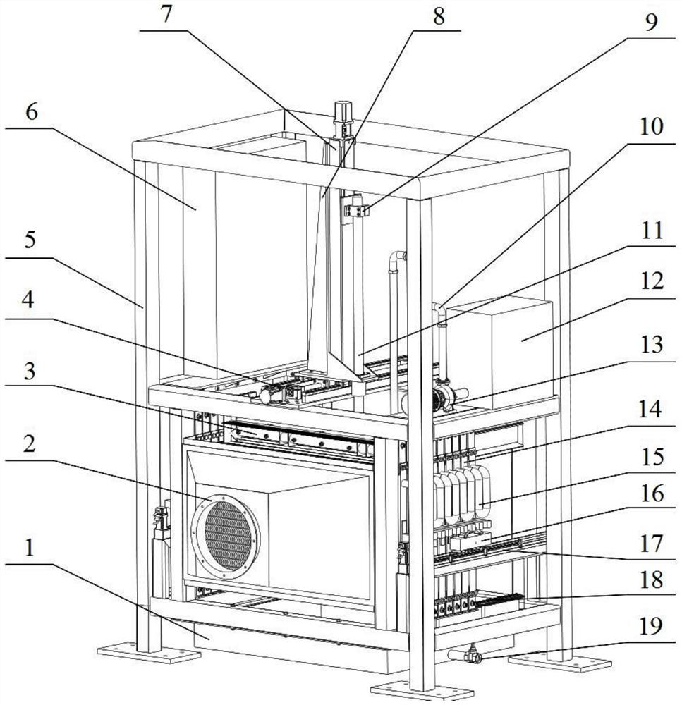
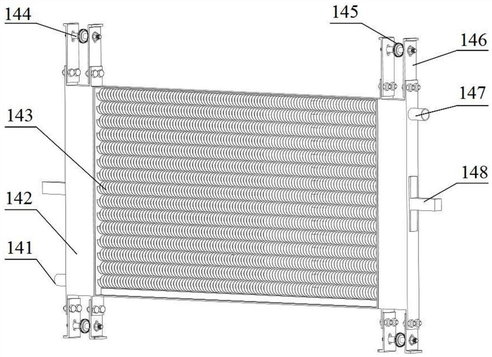
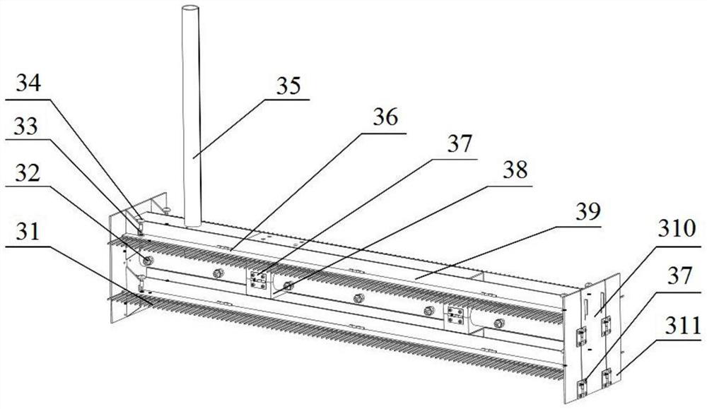
[0024] A self-cleaning exhaust gas waste heat recovery device, combined with figure 1 As shown, it includes a rack 5, the lower part of the front end of the rack 5 is provided with an exhaust gas inlet 2, the lower part of the rear end of the rack 5 is provided with an exhaust gas outlet, and the inside of the rack 5 is provided with a split heat exchanger 14, a quick change The brush cleaning mechanism 3 and the cleaning driving mechanism, the quick brush changing cleaning mechanism 3 and the cleaning driving mechanism are connected with a PLC controller, wherein the exhaust gas inlet 2 is used to connect the high temperature exhaust gas pipeline; the exhaust gas outlet is connected to the exhaust gas discharge pipeline, so as to discharge heat exchange Exhaust gas; the split heat exchanger 14 is arranged between the exhaust gas inlet ...


PUM


Abstract

The invention discloses a self-cleaning waste gas waste heat recovery device, which includes a frame, wherein, the front end of the frame is provided with a waste gas inlet for connecting a high-temperature waste gas pipeline, and the rear end of the frame is provided with a vent for discharging heat exchange waste gas. Exhaust gas outlet; the inside of the frame is provided with a split heat exchanger, a quick-change brush cleaning mechanism and a cleaning drive mechanism; the quick-change brush cleaning mechanism and the cleaning drive mechanism are connected with a PLC for automatic control of the cleaning process controller. The invention can not only recycle the waste heat generated by industrial waste gas, but also perform regular self-cleaning, thereby better solving the problem of waste heat waste, and the cleaning effect is better, the cleaning process is more thorough, and it can also be cleaned according to the actual situation Adjust the degreasing speed, so it is suitable for occasions with more waste heat discharge.

Description

technical field [0001] The invention relates to the technical field of waste heat recovery, in particular to an industrial waste gas waste heat recovery device with a self-cleaning mechanism. Background technique [0002] A large amount of waste gas will be generated in the industrial production process. If it is directly discharged into the atmosphere after being treated by purification equipment, although the impact on air pollution is reduced, the waste heat is not utilized, resulting in a large amount of energy waste. [0003] At present, there are devices for recovering waste heat from exhaust gas on the market, but most waste heat recovery devices for waste gas are mainly aimed at recovering fresh air, and the higher the recovery efficiency, the more complicated the structure of the device. At the same time, if the exhaust gas contains a large amount of oily fibrous substances, after the waste heat recovery device is used for a long time, the oily substances adhere to ...

Claims


Application Information

Patent Timeline
Patent Type & Authority Patents(China)
IPC IPC(8): F28D7/16F28D21/00F28F1/12F28G13/00F28G15/00F28G15/04
CPCF28D7/16F28D21/0003F28F1/12F28G13/00F28G15/003F28G15/04
Inventor 盛永钢李洪涛张彦辉杨林纪运广张天航张钰航
Owner 河北和和能源科技有限公司
Why Eureka
Try Eureka