Abrasive cloth wheel polishing machine for double-sided curve grinding and polishing method of abrasive cloth wheel polishing machine

A technology of curve grinding and emery cloth wheel, which is applied in grinding/polishing equipment, machine tools for surface polishing, grinding/polishing safety devices, etc. It can solve the problems of affecting the efficiency of grinding, scratches on the surface of workpieces, and high cost of use of mechanical arms. problems, to achieve the effect of accelerated grinding efficiency, low cost, and fast fixation

Pending Publication Date: 2021-11-05
盐城市锐克斯研磨科技有限公司
View PDF0 Cites 0 Cited by
  • Summary
  • Abstract
  • Description
  • Claims
  • Application Information

AI Technical Summary

Problems solved by technology

[0005] The object of the present invention is to provide a double-sided curve grinding emery cloth wheel polishing machine and its polishing method, to solve the problem that the existing emery cloth wheel polishing machine proposed in the above-mentioned background technology is a polishing machine driven by a mechanical arm or a hydraulic rod to rotate. The movement of the disc, the mobile grinding on the surface of the curved workpiece, the high cost of the use of the mechanical arm, the hydraulic rod cannot accurately move the polishing disc, resulting in the situation that the polishing disc cannot fit the workpiece or the workpiece is over-pressed, and the surface of the workpiece is accumulated during the polishing process Flattering waste will affect the efficiency of grinding, and it will also easily cause scratches on the surface of the workpiece

Method used


Image

  • Abrasive cloth wheel polishing machine for double-sided curve grinding and polishing method of abrasive cloth wheel polishing machine
  • Abrasive cloth wheel polishing machine for double-sided curve grinding and polishing method of abrasive cloth wheel polishing machine
  • Abrasive cloth wheel polishing machine for double-sided curve grinding and polishing method of abrasive cloth wheel polishing machine

Examples


Embodiment 1

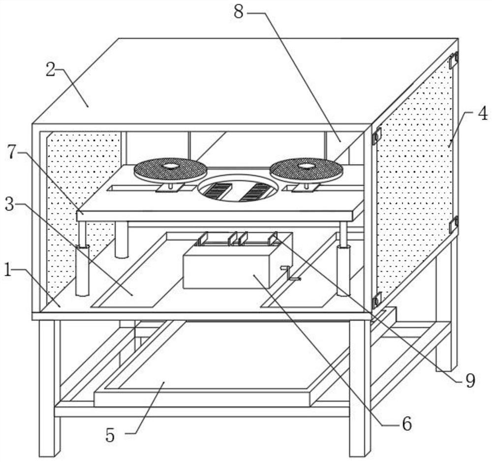
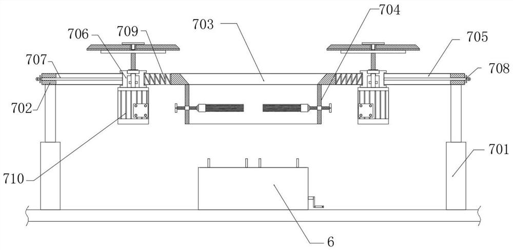
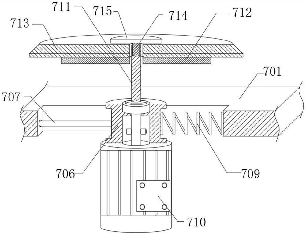
[0033] Please refer to Figure 2- Figure 4 , in the embodiment of the present invention, the grinding assembly 7 includes: four hydraulic rods 701 fixed on the upper end surface of the workbench 1, the upper output ends of the four hydraulic rods 701 are fixed with a support horizontal plate 702, and the support horizontal plate 702 is opened with a through Slot 703, the lower end surface of the supporting horizontal plate 702 is fixed with a connecting pipe 704 connected to the bottom of the through groove 703, and the inside of the supporting horizontal plate 702 is provided with a waist groove 705 symmetrically arranged with respect to the through groove 703; the socket is inserted into the waist groove 705 The sliding block 706 of the cavity, the side of the sliding block 706 away from the through groove 703 is fixed with a pull rod 707, the extended end of the pull rod 707 is fixed with a handle 708, and the side of the sliding block 706 away from the pull rod 707 is fixed...

Embodiment 2

[0035] see Figure 5 The difference from Embodiment 1 is that the collection assembly 8 includes: a suction pipe 801 embedded in the rear end of the protective cover 2, a collection bin 802 is fixed at the rear end of the suction pipe 801, and a suction pipe 802 is embedded in the rear end surface of the collection bin 802. Pump 803; fixed on the draw-in groove 804 at the bottom of the inner chamber of the collection bin 802, the inside of the draw-in groove 804 is sleeved with a multi-purpose filter screen 805 socketed with the collection bin 802; and fixed on one side of the inner cavity of the collection bin 802 and The brush 806 fitted with the multi-purpose filter screen 805, the input end of the suction pipe 801 is set opposite to the grinding yarn wheel 713, and is used to collect the waste impurities generated by the grinding yarn wheel 713 operation. The opening and closing door can also be installed at the feed port, which is used to discharge the accumulated impurit...

Embodiment 3

[0037] see Figure 6 The difference from Embodiment 1 is that the solid material assembly 9 includes: a drive rod 901 that rotates laterally in the inner cavity of the discharge table 6 through a bearing, and the surface of the drive rod 901 is equidistantly engaged with four moving plates 902 through opposite threads. A moving plate 902 upper end surface is fixed with a connecting rod 903 socketed with the discharge platform 6, and the upper end of the connecting rod 903 is fixed with a fixed plate 904; the limit rod 905 is horizontally fixed on the discharge platform 6 inner cavity, and the limit rod 905 is connected to the inner cavity of the discharge platform 6. The upper end of the moving plate 902 runs through the socket, and the side of the discharge platform 6 is socketed with the crank handle 906 fixed with the drive rod 901; The lower end surface of the discharge table 6 is fixed to drive the discharge table 6 to rotate axially. When the handle 906 is rotated in the...


PUM


Abstract

The invention discloses an abrasive cloth wheel polishing machine for double-sided curve grinding. The abrasive cloth wheel polishing machine comprises a workbench, a protective cover, two discharging grooves and a collecting groove; the protective cover is fixed to the upper end face of the workbench, and noise reduction plates are installed on the two sides of an inner cavity of the protective cover in an embedded mode respectively; the two discharging grooves are formed in the surface of the workbench; and the collecting groove is placed at the lower end of the workbench and is oppositely connected with output ends of the discharging grooves. According to the polishing machine, a polishing yarn wheel can be always kept attached to a through groove through a pull ring installed in a kidney groove, when the through groove is connected to the surface of a workpiece in a sleeving mode, the polishing yarn wheel can be always kept in the state of being attached to the curved surface workpiece, and therefore the irregular curved surface can be polished; and the mode that a manipulator or a hydraulic rod needs to be received to drive the position of a polishing disc is changed, the manufacturing cost is low, the surface is accurately polished, meanwhile, a cleaning brush in a connecting pipe can clean the surface of the curved surface workpiece, accumulated impurities are prevented from affecting the polishing efficiency, and the situation of scratching in the polishing process is prevented.

Description

technical field [0001] The invention relates to the field of polishing equipment, in particular to an emery cloth wheel polishing machine for double-sided curve grinding and a polishing method thereof. Background technique [0002] The polishing machine is a kind of electric tool. The polishing machine is composed of basic components such as a base, a throwing disc, a polishing fabric, a polishing cover and a cover. The polishing machine is also called a grinding machine. It is often used for mechanical grinding, polishing and waxing. Its working principle Yes, the motor drives the sponge or wool polishing disc installed on the polishing machine to rotate at high speed. Due to the joint action of the polishing disc and the polishing agent and friction with the surface to be polished, the purpose of removing paint surface pollution, oxide layer, and shallow marks can be achieved. Mechanical Polishing machines are required in the processing field. [0003] In the process of u...

Claims


Application Information

Patent Timeline
IPC IPC(8): B24B29/02B24B55/12B24B41/06B24B41/00B24B1/00
CPCB24B29/02B24B55/12B24B41/06B24B41/00B24B1/00
Inventor 王志成
Owner 盐城市锐克斯研磨科技有限公司
Why Eureka
Try Eureka