
Emergency shutdown control device for air-cooled phase modifier

A control device and emergency shutdown technology, applied in emergency protection circuit device, circuit device, emergency treatment AC circuit layout, etc., can solve the problems of excessive redundancy, different technical routes, unfavorable maintenance, etc., to achieve accurate judgment and strong pertinence , the effect of high reliability

Inactive Publication Date: 2021-11-09
JIANGSU FRONTIER ELECTRIC TECH +1
View PDF0 Cites 0 Cited by
  • Summary
  • Abstract
  • Description
  • Claims
  • Application Information

AI Technical Summary

Problems solved by technology

[0005] However, at present, there are many DCS manufacturers of condensers, with different technical routes, and the processing of emergency shutdown control systems in DCS is also different, and there are even differences between different sites of different DCS manufacturers.
The "two out of three" logic for thermal protection of some condensers is not redundantly configured in terms of input loop, output loop, and controller configuration; Redundant configuration is carried out, but the two-out-of-three logic is implemented in the DCS system and the non-power protection screen of the modulation group. After two out-of-three operations, the redundancy is excessive, which is not conducive to maintenance; the thermal engineering of an air-cooled condenser Most of the logic of protection "two out of three" is implemented in the non-electricity protection screen of the modulation group, but some protections need to perform logic operations in the DCS, so there are still some thermal protections in this station that are exported to the non-electricity after passing through the DCS system The case of the protective screen

Method used


Image

  • Emergency shutdown control device for air-cooled phase modifier
  • Emergency shutdown control device for air-cooled phase modifier
  • Emergency shutdown control device for air-cooled phase modifier

Examples


Embodiment Construction

[0032] The present invention is described in further detail now in conjunction with accompanying drawing.

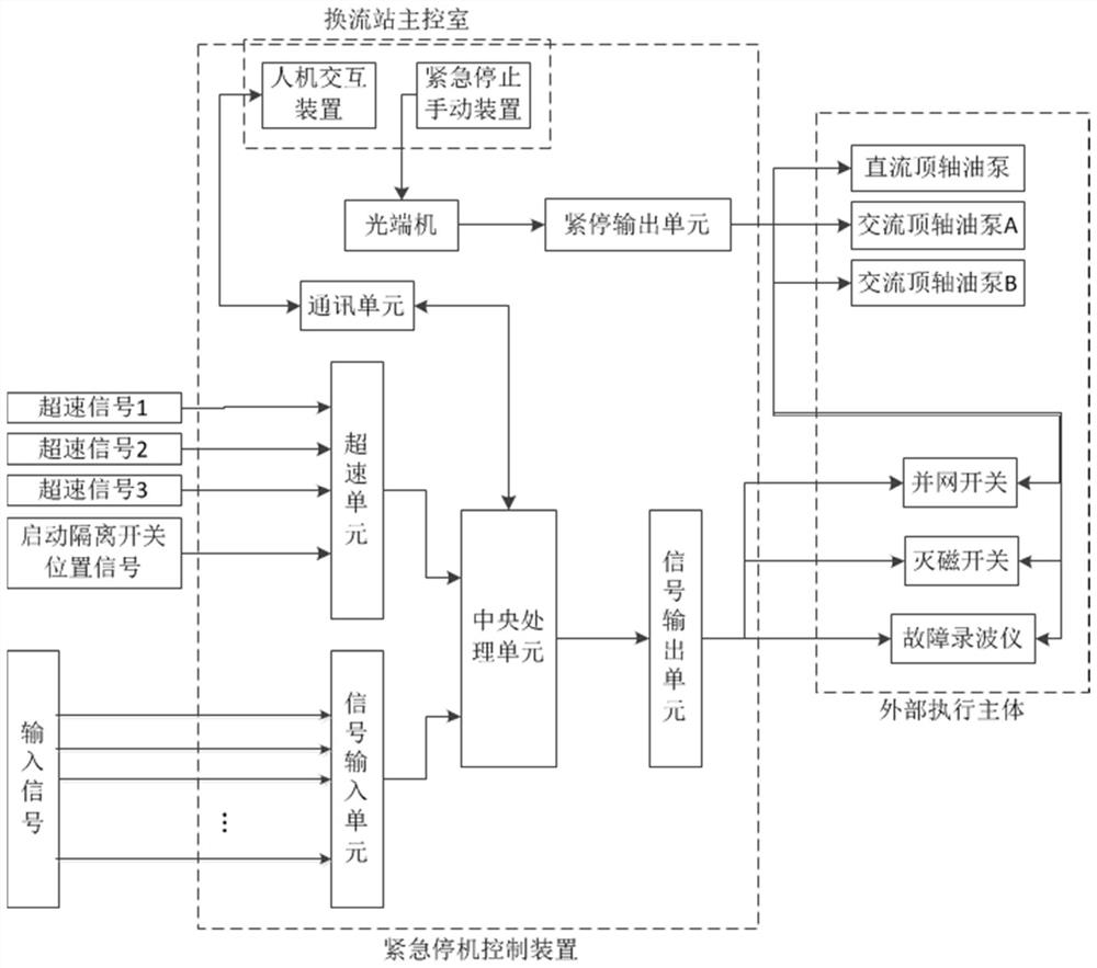
[0033] like figure 1 As shown, the device of the present invention includes a central processing unit, a human-computer interaction device, an emergency stop manual device, a manual emergency stop output unit, a unit overspeed unit, a signal input unit and a signal output unit. U-shaped connectors between units are fixedly connected. in:

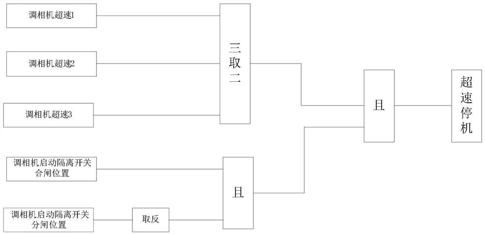
[0034] The overspeed unit of the unit is used to receive the three-way overspeed judgment signal sent by the TSI system and the position signal of the air-cooled condenser to start the isolating switch, and transmit the received signal to the central processing unit for logical judgment to realize overspeed protection;

[0035] The signal input unit is used to receive the vibration monitoring signal and temperature monitoring signal of each point of the air-cooled condenser, and transmit the received signal to the central processing ...


PUM


Abstract

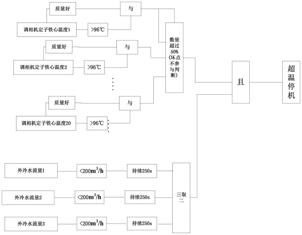
The invention particularly relates to an emergency shutdown control device for an air-cooled phase modifier. The emergency shutdown control device comprises a central processing unit, a man-machine interaction device, an emergency stop manual device, a manual emergency stop output unit, a unit overspeed unit, a signal input unit and a signal output unit. According to the invention, a protection host of the air-cooled phase modifier can be separated from a DCS control system, a control function is realized in the DCS control system, a thermotechnical protection tripping function is realized in the emergency shutdown control device, and when the control system is abnormal, the protection system can still act normally, and the reliability is higher. In the over-temperature protection logic design, the credibility of the iron core temperature signal is added as an auxiliary criterion, and the number of over-temperature iron cores is also considered. Compared with a traditional logic design in which the outer cold water flow is low and the pressure of an outer cold water mother pipe is considered, the design is more targeted, and judgment is more accurate.

Description

technical field [0001] The invention belongs to the technical field of thermal protection, and in particular relates to an emergency shutdown control device for an air-cooled condenser. Background technique [0002] In recent years, the extensive construction of UHV transmission projects has caused changes in the characteristics of the power grid. The response speed of conventional power and electronic equipment is slow, and it cannot quickly provide sufficient dynamic reactive power support for the system during a fault, resulting in a decrease in the system voltage stability margin. The inherent fast dynamic reactive power output characteristics of the condenser just make up for this shortcoming, and it has been re-used in the era of "big power grid", providing strong support for the construction of a backbone power grid with new energy as the main body. [0003] The regulator at the sending end converter station improves the stability of the AC bus voltage through deep p...

Claims


Application Information

Patent Timeline
IPC IPC(8): H02H7/00H02J3/16H02J3/18
CPCH02H7/00H02J3/16H02J3/1885H02J3/001Y02E40/30
Inventor 张卫庆张志宏刘一丹曹扬孙川刘鑫刘娜娜戴兴干
Owner JIANGSU FRONTIER ELECTRIC TECH
Learn More