Additive manufacturing smelting equipment

A smelting equipment and additive manufacturing technology, applied in the field of additive manufacturing, can solve the problems of thermal fatigue effect of surrounding components, reduce component safety, heat dissipation, etc. drain effect

Inactive Publication Date: 2021-11-12
鲁康权
View PDF0 Cites 1 Cited by
  • Summary
  • Abstract
  • Description
  • Claims
  • Application Information

AI Technical Summary

Problems solved by technology

[0005] Aiming at the deficiencies of the prior art, the present invention provides an additive manufacturing smelting equipment, which solves the problem that when the existing additive manufacturing smelting equipment is smelted, the equipment itself is placed outside, and the heat generated by smelting overflows everywhere, resulting in waste of energy , at the same time, the heat will have a thermal fatigue effect on the surrounding components, reducing the safety of the components themselves

Method used


Image

  • Additive manufacturing smelting equipment
  • Additive manufacturing smelting equipment
  • Additive manufacturing smelting equipment

Examples


Embodiment 1

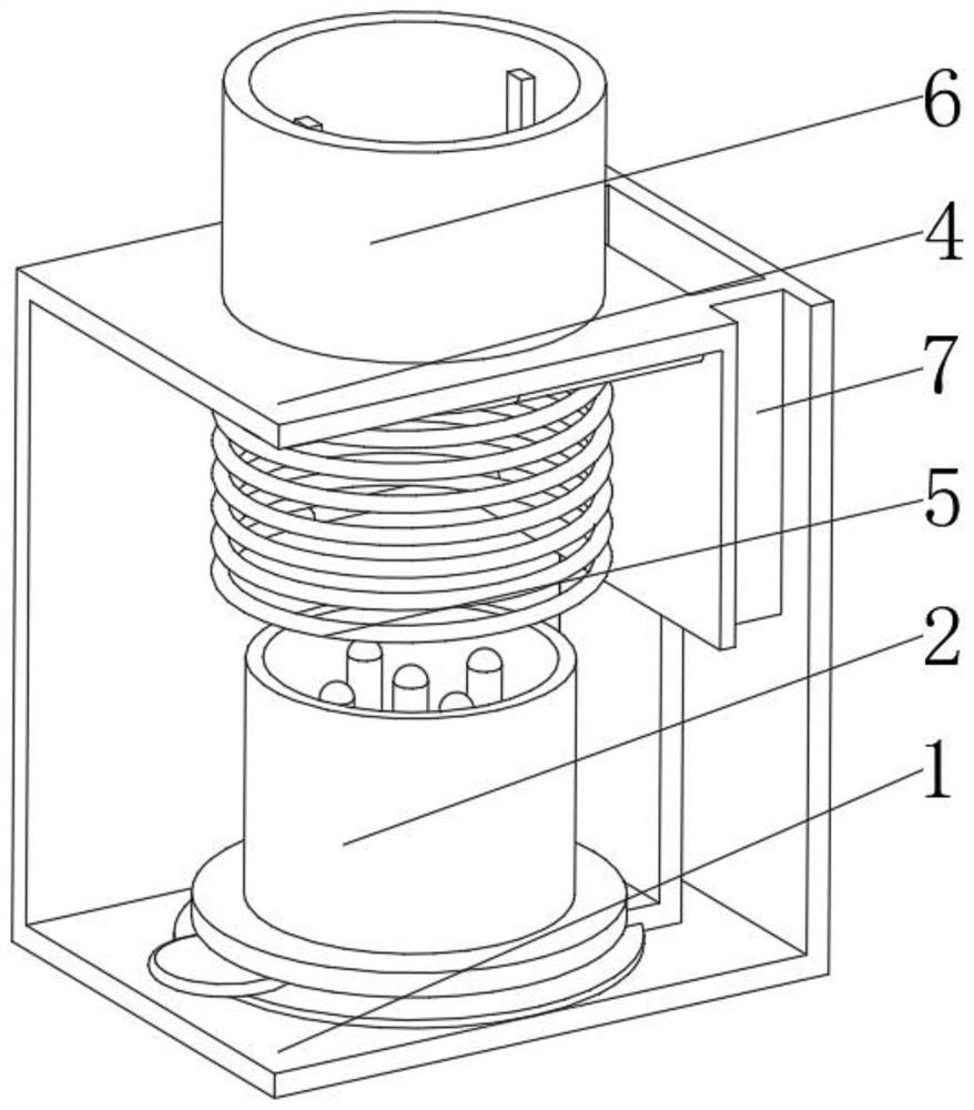
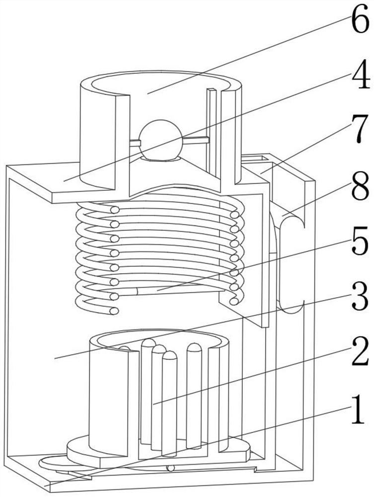
[0038] see Figure 1-3 , the present invention provides a technical solution: a smelting equipment for additive manufacturing, specifically comprising:

[0039] Bottom box seat 1, the bottom box seat 1 has a square seat plate, and a smelting device 2 installed in the middle of the top of the square seat plate, and an L-shaped baffle plate 3 installed on the top of the square seat plate and at the back of the smelting device 2, and The protective top plate 4 installed on the top of the L-shaped baffle 3, and the high-frequency coil 5 installed at the bottom of the protective top plate 4, and the smoke device 6 installed on the top of the protective top plate 4, and installed on the rail limit on the right side of the protective top plate 4 plate 7, and a lifter 8 installed on the inner wall of the L-shaped baffle plate 3 and located in the cavity of the track limiting plate 7. Through the setting of the high-frequency coil 5, the high-frequency eddy current heating is carried ...

Embodiment 2

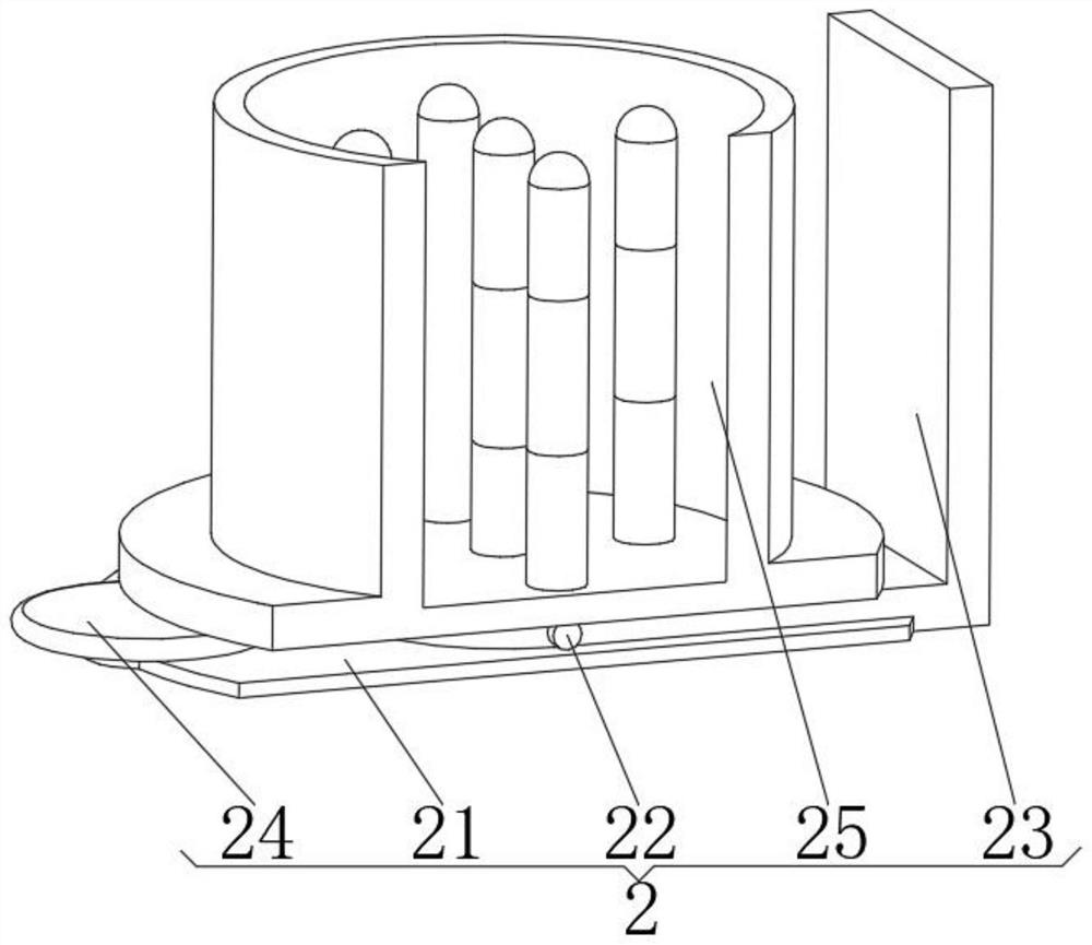
[0048] see Figure 1-5 , on the basis of Embodiment 1, the present invention provides a kind of technical scheme: melting device 25 comprises:

[0049] Turntable base 251, the turntable base 251 has a circular base plate, a built-in device 252 installed in the middle of the top of the circular base plate, and a bearing box 253 installed on the top of the circular base plate and outside the built-in device 252. Through the design of the turntable base 251, the area of ​​the base is increased, the relative height of its own center of gravity is reduced, the stability performance is improved, and the leakage of the internal additive manufacturing raw materials caused by the inclination of the melting device 25 itself during the melting process is avoided, and the surrounding components are protected.

[0050] Built-in devices 252 include:

[0051] Seat column 2521, the seat column 2521 has a cylindrical body, and a heat generating column 2522 installed in the middle of the top o...

Embodiment 3

[0054] see Figure 1-6 , on the basis of Embodiment 1 and Embodiment 2, the present invention provides a technical solution: the flue gas device 6 includes:

[0055] A flue gas cylinder 61, the flue gas cylinder 61 has a cylindrical cylinder, a conical frustum cylinder 62 installed on the inner surface of the cylindrical cylinder, a rotating frame 63 installed on the top of the conical frustum cylinder 62, and a rotating frame 63 installed on the rotating frame 63 close to each other Side auxiliary rod 64, and the closed ball 65 that is installed on the side of auxiliary rod 64 away from rotating frame 63. Through the design of the closed ball 65 and the oblique diversion lines engraved on the surface of the closed ball 65, the component seals the melting device 25 to reduce the rapid loss of heat. At the same time, the closed ball 65 is rotated by the oblique guide lines to slow down the flow of the flue gas and reduce its flow speed, which facilitates the precipitation and ...


PUM


Abstract

The invention discloses additive manufacturing smelting equipment, and relates to the technical field of additive manufacturing. The additive manufacturing smelting equipment specifically comprises a bottom box base, a smelting device installed in the middle of the top of a square base plate, an L-shaped baffle installed on the top of the square base plate and located on the back face of the smelting device, a protective top plate installed on the top of the L-shaped baffle, a high-frequency coil installed at the bottom of the protection top plate, a smoke device installed at the top of the protection top plate, a rail limiting plate installed on the right side of the protection top plate, and a lifter installed on the inner wall of an L-shaped baffle and located in an inner cavity of the rail limiting plate. According to the additive manufacturing smelting equipment, the high-frequency coil is arranged to conduct high-frequency eddy current heating on the whole component, heat of a heating part is concentrated, the rapid smelting efficiency of the high-frequency coil is improved, meanwhile, the high-frequency coil can limit the heat dissipation direction, heat is prevented from being transmitted to the components around the smelting device, and the situation that the components are damaged due to thermal fatigue of the components is avoided.

Description

technical field [0001] The invention relates to the technical field of additive manufacturing, in particular to an additive manufacturing smelting equipment. Background technique [0002] Additive manufacturing, commonly known as 3D printing, is a combination of computer-aided design, material processing and forming technology, based on digital model files, through software and numerical control system, special metal materials, non-metal materials and medical biological materials, according to extrusion, Sintering, melting, light curing, spraying, etc. are accumulated layer by layer to create a manufacturing technology for physical objects. In additive manufacturing, a melting furnace is usually required to melt metal raw materials to provide printing materials for additive manufacturing. During smelting, the equipment itself is placed outside, and the heat generated by smelting overflows everywhere, resulting in a waste of energy. At the same time, the heat has a thermal f...

Claims


Application Information

Patent Timeline
Patent Type & Authority Applications(China)
IPC IPC(8): F27B14/02F27B14/06F27B14/08F27B14/14F27B14/18F27B14/20F27D3/15B22F12/00B33Y40/00
CPCF27B14/02F27B14/061F27B14/14F27B14/20F27B14/08F27B14/0806F27D3/1545B22F12/00B33Y40/00F27B2014/0818Y02P10/25
Inventor 鲁康权
Owner 鲁康权
Why Eureka
Try Eureka