Supercharge Your Innovation With Domain-Expert AI Agents!

Realization method of W-band one-dimensional phase-scanning oblique polarization horn antenna array plane

A technology of a horn antenna and an implementation method, which is applied in the directions of manufacturing antenna array devices, antenna arrays, antennas, etc., can solve the problems of difficulty in the layout design of antenna arrays, and difficulty in realizing uniform linear arrays of horn antennas. Effects of processing requirements

Active Publication Date: 2021-11-12
成都锐芯盛通电子科技有限公司
View PDF9 Cites 0 Cited by
  • Summary
  • Abstract
  • Description
  • Claims
  • Application Information

AI Technical Summary

Problems solved by technology

If oblique polarization is used, the long side of the transmission waveguide is 0.5 Takes 0.35 in the horizontal direction , short side 0.25 Takes 0.18 in the horizontal direction , a total of 0.53 , with a cell spacing of 0.58 The size is equivalent, considering the influence of the horn angle on the gain and the feasibility of array processing, it is difficult to meet the condition that the distance between the antenna elements is smaller than the grating lobes, so it is difficult to realize a uniform linear array of obliquely polarized horn antennas
It can be seen that the array layout design of this antenna array is more difficult

Method used


Image

  • Realization method of W-band one-dimensional phase-scanning oblique polarization horn antenna array plane
  • Realization method of W-band one-dimensional phase-scanning oblique polarization horn antenna array plane
  • Realization method of W-band one-dimensional phase-scanning oblique polarization horn antenna array plane

Examples


Embodiment Construction

[0036] The technical solutions of the present invention will be clearly and completely described below in conjunction with the embodiments. Apparently, the described embodiments are only some of the embodiments of the present invention, not all of them. Based on the embodiments of the present invention, all other embodiments obtained by those skilled in the art without making creative efforts belong to the protection scope of the present invention.

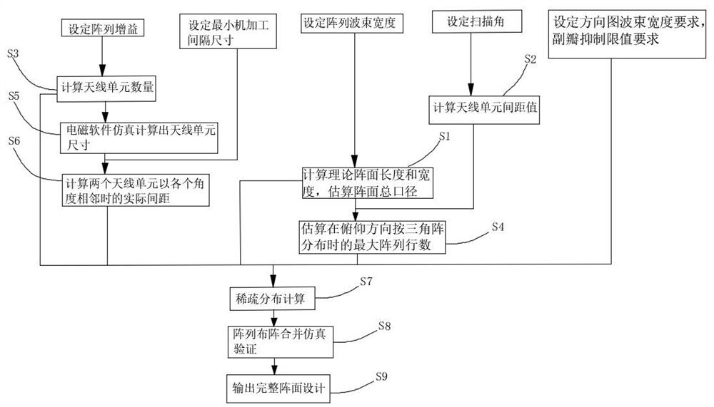
[0037] The present invention provides a technical solution: a method for realizing a one-dimensional phase-scanned obliquely polarized horn antenna array in the W frequency band, wherein the antenna array is a one-dimensional phase-swept array working in the W frequency band, and the antenna array is composed of The antenna unit is an obliquely polarized horn antenna unit, and this embodiment adopts a horn antenna unit with a rectangular aperture.

[0038] Such as figure 1 As shown, the implementation method steps are as follows:...


PUM


Abstract

The invention discloses an implementation method of a W-band one-dimensional phase-scanning oblique polarization horn antenna array plane, belonging to the technical field of antennas. The implementation method comprises the following steps: S1, respectively calculating a corresponding length L1 and a corresponding length L2 according to two target beam width values, and estimating the total aperture of the array plane; S2, calculating an antenna unit spacing value d according to a set target scanning angle value; S3, setting array gain G and estimating the number N of array plane antenna units; S4, estimating a line number of arrangable arrays when a pitching direction is distributed according to a triangular array; S5, simulating the sizes of the antenna units; S6, calculating actual spacing between oblique polarization antenna units when the oblique polarization antenna units are adjacent at each angle; S7, conducting sparse distribution design; S8, constructing the antenna units according to the antenna unit sizes simulated in the step S5, and arranging the antenna units according to a sparse distribution result in the step S7; and S9, designing an output array plane. Through combination of the triangular array and sparse array arrangement, the obtained antenna array surface realizes good azimuth sidelobe suppression and pitching coverage effects.

Description

technical field [0001] The invention relates to a method for realizing a W-band one-dimensional phase-swept obliquely polarized horn antenna array, and belongs to the technical field of antennas. Background technique [0002] The millimeter wave band has been extensively researched and developed due to its advantages of broadband, narrow beam, and strong anti-interference ability, and has important application value in the fields of modern communication and radar. Among them, the W frequency band (usually defined as millimeter wave between 60~110GHz) is more suitable for the development trend of antenna integration and miniaturization because of its short wavelength, usually between 3-5mm, and correspondingly produces W frequency band electronic countermeasure technology necessary for development. In addition, in modern radar applications, horizontally or vertically polarized antennas are usually used. According to the antenna theory, the efficiency of the transmitting ante...

Claims


Application Information

Patent Timeline
IPC IPC(8): H01Q21/00H01Q13/02
CPCH01Q21/0087H01Q13/0283
Inventor 吴凡胡斌刘聪
Owner 成都锐芯盛通电子科技有限公司
Features
  • R&D
  • Intellectual Property
  • Life Sciences
  • Materials
  • Tech Scout
  • Unparalleled Data Quality
  • Higher Quality Content
  • 60% Fewer Hallucinations
Learn More