Cooling device for optical fiber drawing

A cooling device and wire drawing technology, applied in the direction of manufacturing tools, glass manufacturing equipment, etc., can solve the problems of reducing the cooling effect, temperature rise, temperature rise, etc., to achieve the effect of enhancing the cooling effect, enhancing the cooling capacity, and increasing the duration of action

Pending Publication Date: 2021-11-16
郭俊滔
View PDF11 Cites 3 Cited by
  • Summary
  • Abstract
  • Description
  • Claims
  • Application Information

AI Technical Summary

Problems solved by technology

[0003] With the increase of the length of single wire drawing and the increase of wire drawing speed, there is a higher requirement for the cooling capacity of the existing wire drawing tower. The existing cooling device generally realizes cooling by feeding cooling gas and supplementing water cooling. , the gas introduced is generally helium, hydrogen or nitrogen, but the application cost of helium is higher, the risk of hydrogen is higher, and there are higher requirements for plant and management, while the specific heat of nitrogen is lower, and the heat dissipation The effect is poor, and there is no perfect cooling device after comprehensive consideration
[0004] Secondly, due to the high height of the drawing tower, when cooling, the cooling gas passes through the drawing tower, and the temperature will rise greatly. Although the cooling is supplemented by water cooling to control the gas temperature, the temperature of the gas will still rise, especially In the vicinity of the optical fiber, a boundary layer is formed, which isolates the fresh cold air and further reduces the cooling effect

Method used


Image

  • Cooling device for optical fiber drawing
  • Cooling device for optical fiber drawing
  • Cooling device for optical fiber drawing

Examples


Embodiment 1

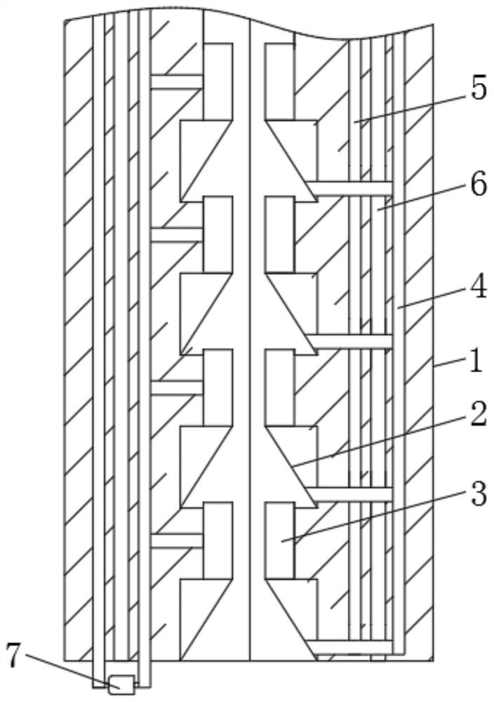
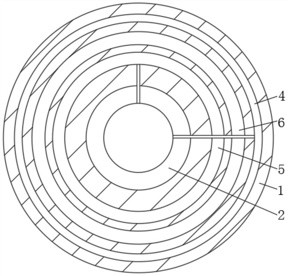
[0021] see Figure 1-2 , a cooling device for optical fiber drawing, comprising a tower body 1, the inner cavity of the tower body 1 injects cooling gas, and the inner wall of the tower body 1 is continuously provided with a cooling unit composed of an air blowing part 2 and an air suction part 3 from top to bottom , and in each unit, the suction piece 3 is arranged upstream of the blowing piece 2, with respect to the air-cooling flow direction, the blowing piece 2 and the suction piece 3 are respectively connected with an air outlet channel 4 and an air suction channel 5, and the blowing piece 2. The suction part 3, the air outlet channel 4 and the air suction channel 5 form an air-cooling cycle, that is, the cooling gas is sucked by the suction part 3, passes through the suction channel 5 and the air outlet channel 4, and then flows back through the suction part 3 To the inner chamber of the tower body 1, the optical fiber is cooled. The tower body 1 is provided with a water...

Embodiment 2

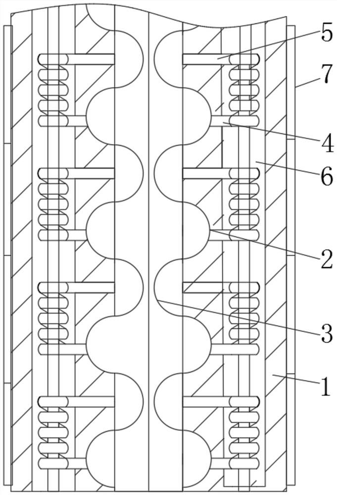
[0025] The difference from Embodiment 1 is that please refer to image 3 with Figure 4 , the blowing part 2 and the suction part 3 are both airbags, and the blowing part 2 is recessed toward the inner wall, and the suction part 3 protrudes toward the inner cavity. 7 is an electromagnet located on the side wall of the tower body 1, the electromagnet drives the magnet, and then drives the blowing part 2 and the suction part 3 to compress and relax, and the formation of the blowing part 2 and the suction part 3 is opposite, that is, the blowing part 2 When compressed, the suction part 3 relaxes, and a one-way valve is provided between the blowing part 2 and the suction part 3 and between the blowing part 2 and the suction part 3, and the blowing part 2 exhausts in one direction, and the suction The part 3 sucks air in one direction, and the gas flows from the suction part 3 to the blowing part 2 in one direction. Compared with the first embodiment, the gas flow path is shorter,...


PUM


Abstract

The invention relates to the technical field of optical fiber drawing equipment, and discloses a cooling device for optical fiber drawing, which comprises a tower body, the inner wall of the tower body is continuously provided with a cooling unit consisting of an air blowing part and an air suction part from top to bottom, and in each unit, the air suction part is arranged at the upstream of the air blowing part, and the air suction part is arranged at the downstream of the air blowing part. The air blowing part and the air suction part are connected with an air outlet channel and an air suction channel respectively. According to the cooling device for optical fiber drawing, after the cooling gas is introduced, the gas repeatedly rolls in the cavity, so that the acting time of the gas is greatly prolonged, the use amount of the cooling gas is reduced, the cooling device is particularly suitable for helium with higher value, and the cooling requirement can be met only by using a small amount of gas; the air continuously performs small circulation in the cooling unit formed by the air blowing part and the air suction part, the air always keeps low temperature in the circulation, and secondly, the flow speed is increased, so that a boundary layer around the optical fiber can be directly damaged, the air is uniformly mixed, and the cooling capacity is further enhanced.

Description

technical field [0001] The invention relates to the technical field of optical fiber drawing equipment, in particular to a cooling device for optical fiber drawing. Background technique [0002] When manufacturing an optical fiber, it is first necessary to melt the optical fiber preform, maintain a certain tension for drawing, and then take up the wire after cooling, coating, and curing devices to become a semi-finished optical fiber. After the optical fiber leaves the drawing furnace, the temperature is relatively high. , in order to ensure the coating and curing effect, the fiber needs to be cooled when it leaves the drawing furnace. [0003] With the increase of the length of single wire drawing and the increase of wire drawing speed, there is a higher requirement for the cooling capacity of the existing wire drawing tower. The existing cooling device generally realizes cooling by feeding cooling gas and supplementing water cooling. , the gas introduced is generally heli...

Claims


Application Information

Patent Timeline
Patent Type & Authority Applications(China)
IPC IPC(8): C03B37/027C03B37/10
CPCC03B37/027C03B37/10
Inventor 郭俊滔
Owner 郭俊滔
Why Eureka
Try Eureka