Differential interference contrast microscopic endoscopic imaging system and endoscopic imaging method

A differential interference and imaging system technology, applied in the analysis of materials, material analysis by optical means, measurement devices, etc., can solve the problem of inability to accurately observe ultra-fine surface contours for industrial inspection, inaccurate diagnosis of diseased tissue, and difficulty in providing sample surfaces. details, etc.

Pending Publication Date: 2021-11-19
ZHEJIANG LAB +1
View PDF0 Cites 1 Cited by
  • Summary
  • Abstract
  • Description
  • Claims
  • Application Information

AI Technical Summary

Problems solved by technology

[0005] The purpose of the present invention is to provide a differential interference contrast microscopic endoscopic imaging system and endoscopic imaging method, which solves the problem that in the prior art it is difficult to

Method used


Image

  • Differential interference contrast microscopic endoscopic imaging system and endoscopic imaging method
  • Differential interference contrast microscopic endoscopic imaging system and endoscopic imaging method
  • Differential interference contrast microscopic endoscopic imaging system and endoscopic imaging method

Examples


Embodiment 1

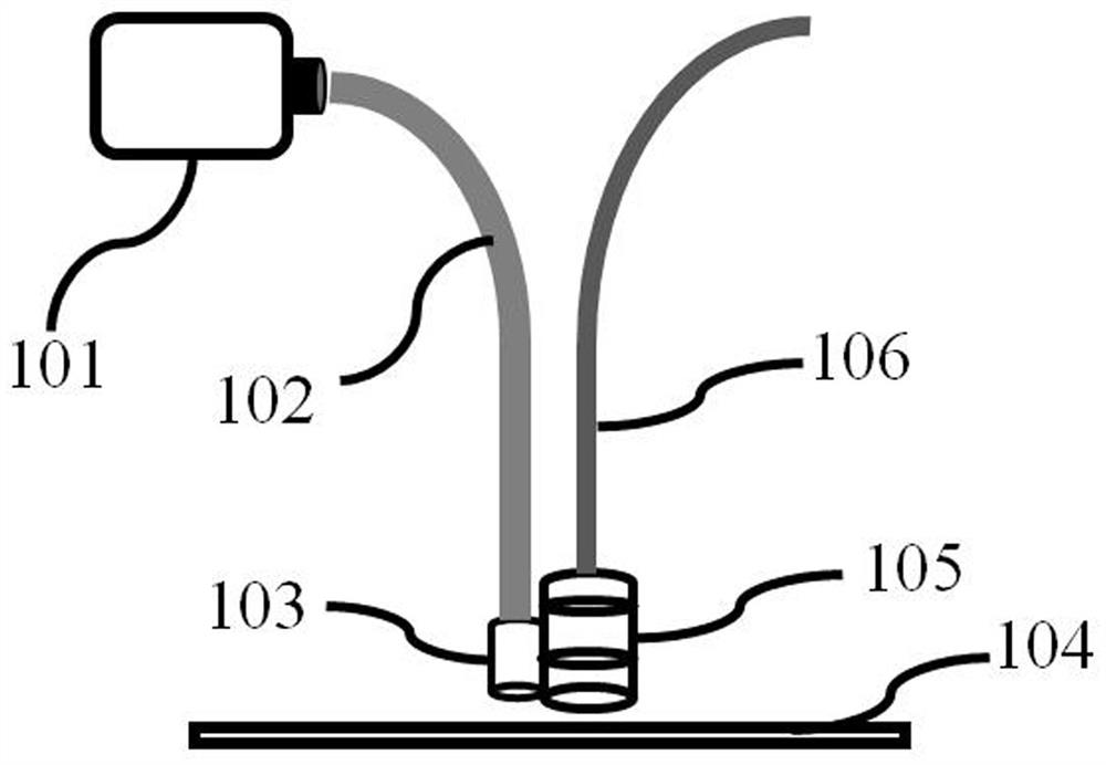
[0071] Example 1, see Figure 1-Figure 4 :

[0072] The illumination light source 101 is selected from LD (laser diode) light sources, the optical fiber 102 is selected from quartz optical fibers, the observed sample 104 is selected from human tissue, and the imaging detector 211 is selected from COMS (complementary metal oxide semiconductor) detectors. The differential interference prism 204 and the second differential interference prism 207 are selected from Wollaston prisms.

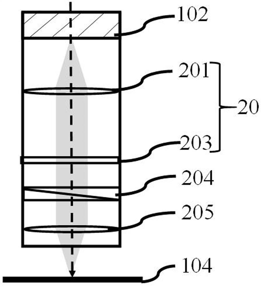
[0073] The illumination optical path module 103 includes a lens assembly 201, a polarizer 202, a first 1 / 4 wave plate 203, a first differential interference prism 204, and an illumination objective lens 205 arranged in sequence from top to bottom, and the imaging receiving module 105 includes a bottom-to-top Imaging objective lens 206 , second differential interference prism 207 , second 1 / 4 wave plate 208 , analyzer 209 , tube lens 210 and imaging detector 211 are arranged in sequence.

[0074] Amo...

Embodiment 2

[0080] Example 2, see Figure 1-Figure 2 , Figure 5-Figure 6 :

[0081] The illumination source 101 is selected from polarized light sources, the observed sample 104 is selected from human tissue, the imaging detector 211 is selected from CCD (charge-coupled device) detectors, the first differential interference prism 204 and the second differential interference prism 207 are selected from Noma Nomarski prism, the optical fiber 102 is selected from the polarization maintaining fiber, because the light emitted by the optical fiber 102 is polarized light, so the polarizer 202 is omitted.

[0082] The illumination optical path module 103 includes a lens assembly 201, a first 1 / 4 wave plate 203, a first differential interference prism 204, and an illumination objective lens 205 arranged sequentially from top to bottom, and the imaging receiving module 105 includes an imaging objective lens arranged sequentially from bottom to top 206 , the second differential interference prism...


PUM


Abstract

The invention discloses a differential interference contrast microscopic endoscopic imaging system and an endoscopic imaging method. The microscopic endoscopic imaging system comprises an illumination light source, an optical fiber, an illumination light path module, an imaging receiving module and a cable. The method has the remarkable characteristics that the contrast ratio of an observed object is enhanced, the technology utilizes a differential interference prism to generate ordinary light (o light) and extraordinary light (e light), the two beams of coherent light change the optical path difference after passing through the object and interfere with each other on an image plane, so that the tiny change of the surface height of a sample is shown in the form of strong light intensity change on an interference background, an embossment sense is formed, and the microcosmic contour of the surface of the sample can be visually reflected. The differential interference microscopy technology can realize nanoscale phase resolution of the surface of the sample, observes the fine structure of the surface of the sample, and helps doctors to judge focus characteristics according to surface fluctuation characteristics of the observed sample and make diagnosis.

Description

technical field [0001] The invention relates to the technical field of optical microscopic endoscopic imaging, in particular to a differential interference contrast microscopic endoscopic imaging system and an endoscopic imaging method. Background technique [0002] Endoscope is an integrated endoscopic imaging device that integrates various technologies such as optics, precision machinery, electronic circuits, software and algorithms. An endoscope is usually composed of several parts such as a mirror body, an illumination system, an operation insertion part, and a host system. Endoscopes can be divided into medical endoscopes and industrial endoscopes according to different usage scenarios. Among them, the medical endoscope enters the human body through the natural orifice of the human body or the percutaneous puncture channel to observe the lesions of the relevant parts, assist the doctor to make a diagnosis of the lesions or take a biopsy of the lesions for pathological ...

Claims


Application Information

Patent Timeline
IPC IPC(8): G01N21/47G01N21/01
Inventor 庞陈雷杨青王智王立强
Owner ZHEJIANG LAB
Why Eureka
Try Eureka