Clamping tool for servo motor driver maintenance

A technology of servo motors and drives, which is applied to workbenches, manufacturing tools, cleaning methods and appliances, etc. It can solve the problems of inability to adjust, no clamping of servo motor drives, single structure, etc., and achieve the effect of easy maintenance

Active Publication Date: 2021-11-23
安徽智鸥驱动科技有限公司
View PDF6 Cites 0 Cited by
  • Summary
  • Abstract
  • Description
  • Claims
  • Application Information

AI Technical Summary

Problems solved by technology

[0004] During the maintenance of the servo motor driver, in order to facilitate the maintenance of the servo motor driver, it needs to be fixed and clamped reasonably, so as to facilitate the fixed support of the servo motor driver during maintenance, and it is convenient to handle the servo motor driver during maintenance, but the traditional clamping is due to the single structure , only play a fixed role, resulting in the inability to adjust according to the different sizes of the servo motor drive, unable to meet the current needs for fixed clamping of the servo motor drive, resulting in no reasonable clamping of the servo motor drive, hindering the maintenance of the servo motor drive

Method used


Image

  • Clamping tool for servo motor driver maintenance
  • Clamping tool for servo motor driver maintenance
  • Clamping tool for servo motor driver maintenance

Examples


Embodiment 1

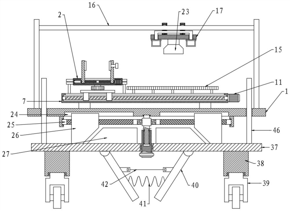
[0036] Please refer to the accompanying drawings, the present invention provides a technical solution: a tooling clamp for servo motor driver maintenance, including a workbench 1, a fixed assembly and a moving assembly are arranged on the workbench 1, and a support frame 16 is provided above the workbench 1 to support A blower 23 is provided below the frame 16, a base plate 37 is provided below the workbench 1, a lifting assembly is provided between the workbench 1 and the base plate 37, and some support columns 38 are provided below the bottom surface of the base plate 37.

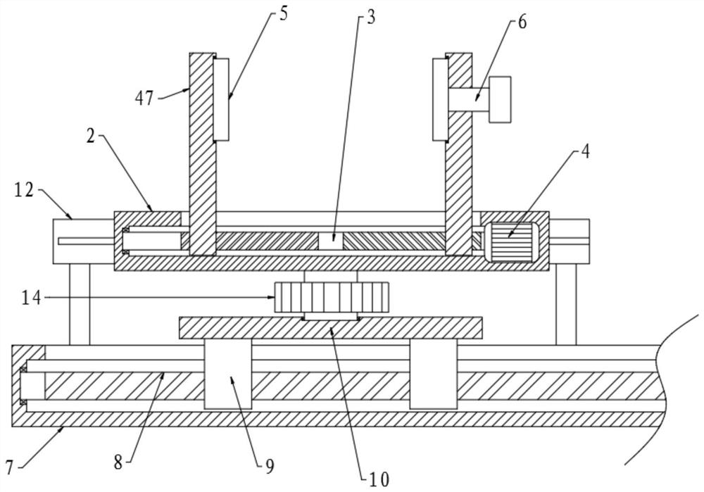
[0037] Wherein, the fixed assembly includes a fixed box 2, and the inside of the fixed box 2 is connected to a No. 1 screw mandrel 3 for rotation, and the right end of the No. 1 screw mandrel 3 is connected to a No. 1 motor 4, and the thread directions on the left and right sections of the No. 1 screw mandrel 3 are opposite. And be respectively threaded with fixed frame 47, the upper end of fixed frame 47 ...

Embodiment 2

[0043] The structure of this embodiment is basically the same as that of Embodiment 1, the difference is that the top of the blower 23 is fixed with a loading plate 17, and there are two sliding tubes 18 on the left and right above the loading plate 17, and the inside of the sliding tube 18 is Sliding sleeve limited tube 19, the top of the loading plate 17 is provided with a control rod 20, the bottom ends of the left and right sides of the control rod 20 all slide downwards to stretch out the loading plate 17, and are fixed with a pull ring 22, the control rod 20 passes through the sliding tube 18 and is slidably connected in the sliding tube 18 in the vertical direction. The bottom end of the limit tube 19 is fixed above the control rod 20, and the bottom surface of a section in the sliding tube 18 on the control rod 20 is fixed. There is a No. 1 spring 21 , and the upper part of the support frame 16 passes through the sliding tube 18 and the limit tube 19 .

[0044] The sta...

Embodiment 3

[0046] The structure of this embodiment is basically the same as that of Embodiment 1. The difference is that the lifting assembly includes a rotating shaft 25 rotatably connected to the bottom surface of the workbench 1. The left and right sections of the rotating shaft 25 are provided with threads in opposite directions, and the middle part is provided with There is a worm 28, and the left and right sides of the bottom surface of the workbench 1 are provided with chute 24, and the chute 24 is slidably connected with a moving inclined block 26. Connected on the left and right sections of the rotating shaft 25, the left and right sides of the top surface middle part of the bottom plate 37 are provided with fixed inclined blocks 27 corresponding to the movable inclined blocks 26, and the front side of the workbench 1 is also provided with a control mechanism.

[0047] Wherein, the middle of the bottom surface of the workbench 1 is rotatably connected with a rotating rod 30, the ...


PUM


Abstract

The invention discloses a clamping tool for servo motor driver maintenance in the technical field of clamping tools for maintenance. The clamping tool comprises a workbench, wherein a fixed assembly and a movable assembly are arranged on the workbench; a supporting frame is arranged above the workbench; an air blower is arranged below the supporting frame; a bottom plate is arranged below the workbench; a lifting assembly is arranged between the workbench and the bottom plate; and a plurality of supporting columns are arranged below the bottom surface of the bottom plate. According to the clamping tool disclosed by the invention, the fixed assembly and a rotary plate are arranged, a servo motor driver is placed on a fixed box, and a motor I drives a lead screw I to rotate, so that fixed frames at the two sides are driven to move inwards; the rotary plate on the fixed frames fixes the servo motor driver in the middle; and a rotary handle is rotated to drive the rotary plate to rotate, so that the servo motor driver is driven to rotate, and an angle is regulated, and therefore, a worker conveniently maintains the servo motor driver from different angles.

Description

technical field [0001] The invention relates to the technical field of tool clamping for maintenance, in particular to tool clamping for servo motor driver maintenance. Background technique [0002] The servo motor can control the speed and position accuracy very accurately, and can convert the voltage signal into torque and speed to drive the control object. The rotor speed of the servo motor is controlled by the input signal and can respond quickly. In the automatic control system, it is used as an actuator, and has the characteristics of small electromechanical time constant and high linearity. It can convert the received electrical signal into the motor shaft. The angular displacement or angular velocity output. It is divided into two categories: DC and AC servo motors. Its main feature is that there is no self-rotation phenomenon when the signal voltage is zero, and the speed decreases at a uniform speed with the increase of torque. [0003] The driver of the servo mo...

Claims


Application Information

Patent Timeline
Patent Type & Authority Applications(China)
IPC IPC(8): B25H1/08B25H1/10B25H1/16B25H5/00B08B5/02
CPCB25H1/08B25H1/10B25H1/16B25H5/00B08B5/02Y02E10/72
Inventor 陈凡崔德新张志峰
Owner 安徽智鸥驱动科技有限公司
Why Eureka
Try Eureka