Construction method for assembling steel bar truss composite floor of reinforced concrete frame structure

A technology of reinforced concrete and reinforced concrete beams, which is applied to the on-site preparation of floor slabs, structural elements, and building components, can solve the problems of low construction efficiency, long construction period, and easy occurrence of blasting, so as to improve construction efficiency and shorten the The construction period and the effect of improving the bearing capacity

Active Publication Date: 2021-11-23
GUANGZHOU HENGSHENG CONSTR ENG
View PDF11 Cites 0 Cited by
  • Summary
  • Abstract
  • Description
  • Claims
  • Application Information

AI Technical Summary

Problems solved by technology

[0006] Aiming at the problems existing in the prior art, the steel truss floor slab has a long construction period, low construction efficiency, limited load capacity of the superstructure, affects the construction and construction quality of the floor, has construction safety hazards, and does not consider the steel truss floor slab. The transmitted load at the end of the floor is supported and prone to grout explosion. The technical problem to be solved by the present invention is to provide a structure that can shorten the construction period, improve construction efficiency, and install a support bracket to bear the self-weight and construction load of the poured floor concrete , and assist the floor slab to bear the load transmitted from the upper floor, ensure the progress of the construction progress, improve the construction safety, strengthen the side formwork to withstand the end load of the floor slab transmitted by the steel truss floor slab, and prevent the concrete from bursting Construction method for assembly of reinforced truss composite floor slabs for reinforced concrete frame structures

Method used


Image

  • Construction method for assembling steel bar truss composite floor of reinforced concrete frame structure
  • Construction method for assembling steel bar truss composite floor of reinforced concrete frame structure
  • Construction method for assembling steel bar truss composite floor of reinforced concrete frame structure

Examples


Embodiment 1

[0083] like Figure 21 As shown, the steel bar truss floor deck 7 of the present invention includes a bottom formwork 71 and a steel bar truss 72, and the bottom formwork 71 and the steel bar truss 72 are welded together. 722 is still upper and lower parallel settings, and the web reinforcement 723 arranged between the upper chord reinforcement 721 and the lower chord reinforcement 722 is a non-continuous web reinforcement 723, and the purpose of being designed as a discontinuous web reinforcement 723 is to save reinforcement materials. Thereby reducing costs.

Embodiment 2

[0085] like Figure 22 As shown, the reinforced truss floor deck 7 of the present invention includes a support bar 73, and the support bar 73 includes a support transverse bar 731 and a support vertical bar 732, and the support transverse bar 731 and the support vertical bar 732 are welded together.


PUM

PropertyMeasurementUnit
Thicknessaaaaaaaaaa
Thicknessaaaaaaaaaa

Abstract

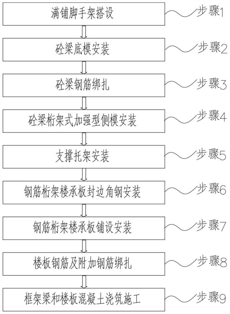
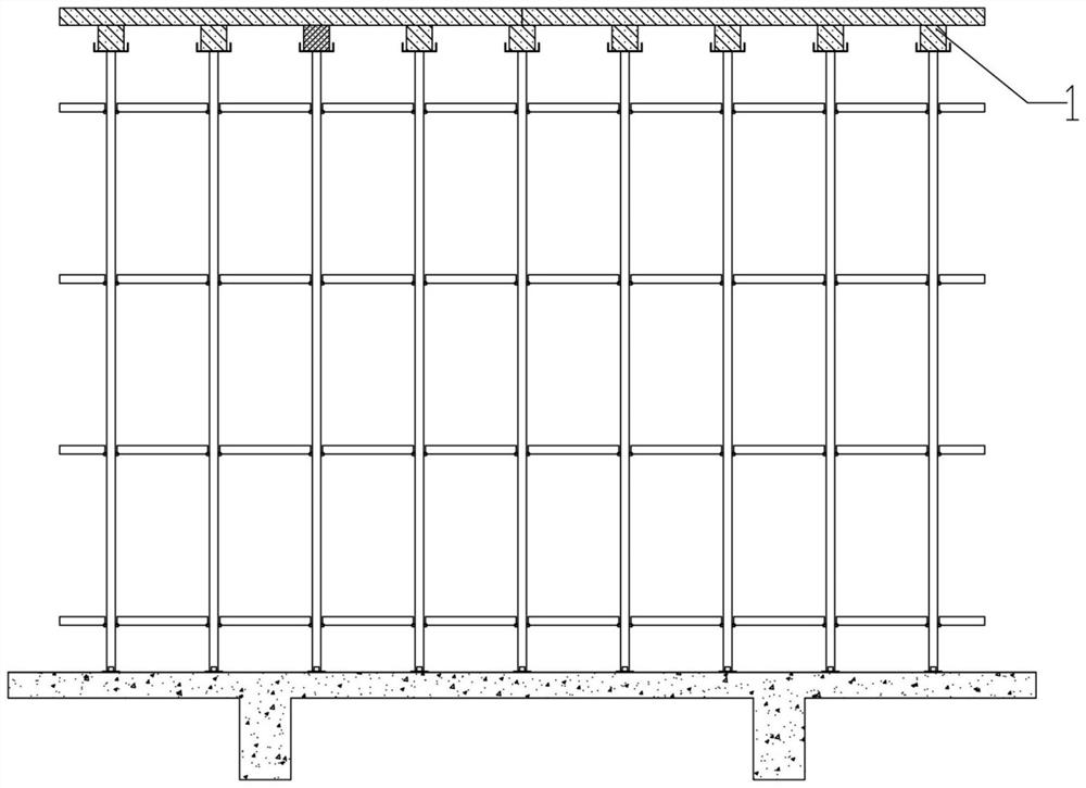
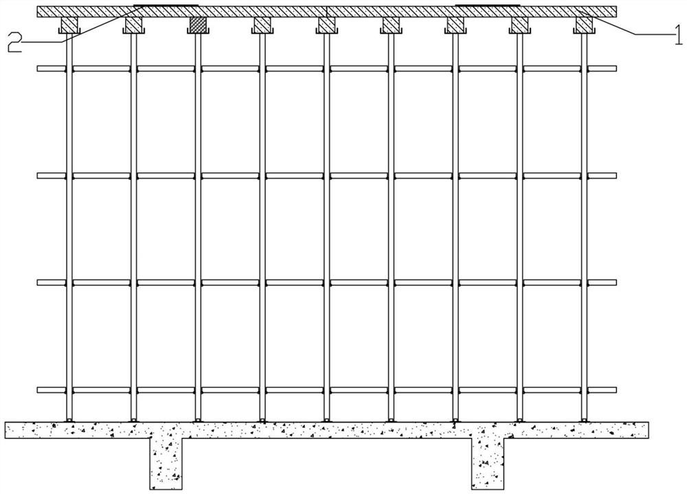
The invention discloses a construction method for assembling a steel bar truss composite floor of a reinforced concrete frame structure. The construction method is applied to the reinforced concrete frame structure, a structural beam of the reinforced concrete frame structure is a cast-in-place reinforced concrete beam, and the floor of the reinforced concrete frame structure is assembled by a steel bar truss floor support plate. The construction method comprises the steps of building of a fully-laid scaffold, installation of a concrete beam bottom die, binding of concrete beam steel bars, installation of a concrete beam truss type reinforced side die, installation of a supporting bracket, installation of steel bar truss floor support plate edge sealing angle steel, laying and installation of a steel bar truss floor support plate, binding of floor steel bars and additional steel bars, and pouring construction of frame beams and floor concrete. By means of the construction method, fabricated construction of the steel bar truss floor support plate can be achieved in the reinforced concrete frame structure, the call of vigorously popularized fabricated buildings in China is effectively responded, the field construction efficiency is improved, the construction period is shortened, and the construction progress is accelerated.

Description

technical field [0001] The invention relates to the technical field of assembling reinforced truss composite floors, in particular to a construction method for assembling reinforced truss composite floors for reinforced concrete frame structures. Background technique [0002] At present, the floor forms of high-rise buildings or floor building systems mainly include cast-in-place concrete floor slabs or reinforced truss floor slabs. The traditional floor slab construction process is mainly: in the cast-in-place reinforced concrete frame structure, by erecting scaffolding, laying a steel truss floor slab above the scaffold, pouring concrete above the steel truss floor slab, pouring concrete and superstructure through the steel truss floor slab Bearing the load transmitted by the object. [0003] There are some problems in the traditional floor slab construction technology: the construction period is long and the construction efficiency is low. In addition, when the steel tru...

Claims


Application Information

Patent Timeline
IPC IPC(8): E04B5/40E04B1/38E04C5/03E04G11/36E04G11/50E04G21/02E04G21/14E04G21/12
CPCE04B5/40E04B1/38E04C5/03E04G11/36E04G11/50E04G21/02E04G21/14E04G21/123
Inventor 曾佳李慧莹李明黄亮忠伍俊锋王诗铖李向勇张伟庭毛鹏孔庆娜
Owner GUANGZHOU HENGSHENG CONSTR ENG
Why Eureka
Try Eureka