A compact low magnetic compression ratio magnetron injection electron gun

A technology of magnetron injection and electron gun, which is applied in the direction of time-of-flight electron tubes, circuits, discharge tubes, etc., can solve the problems of large size of electron guns, achieve the effects of reducing area, overcoming the decrease of electron velocity ratio, and increasing the initial lateral velocity

Active Publication Date: 2022-05-03
UNIV OF ELECTRONICS SCI & TECH OF CHINA
View PDF0 Cites 0 Cited by
  • Summary
  • Abstract
  • Description
  • Claims
  • Application Information

AI Technical Summary

Problems solved by technology

[0004] The purpose of the present invention is to provide a compact low magnetic compression ratio magnetron injection electron gun to solve the problem of excessive size of the low frequency band magnetron injection electron gun in the prior art

Method used


Image

  • A compact low magnetic compression ratio magnetron injection electron gun
  • A compact low magnetic compression ratio magnetron injection electron gun
  • A compact low magnetic compression ratio magnetron injection electron gun

Examples


Embodiment Construction

[0030] In order to more clearly understand the above objects, features and advantages of the present invention, the present invention will be further described in detail below in conjunction with the accompanying drawings and embodiments.

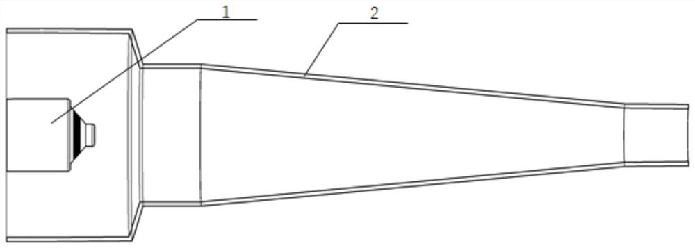
[0031] The invention provides a compact low magnetic compression ratio magnetron injection electron gun, such as figure 2 As shown, including the electron gun body as the anode and the cathode. The anode is a hollow metal shell with a traditional linear tapered structure. The cathode 3 and the anode are located inside the electron gun body and arranged coaxially with the anode.

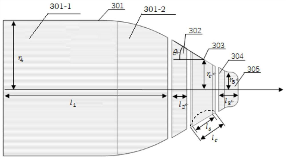
[0032] The cathode is a solid matrix with a structure such as image 3 As shown, the cathode includes a rear forming pole 301, an emitter band 303 and a front forming pole 305; the rear forming pole 301, the emitter segment 303 and the front forming pole 305 are smoothly connected in sequence along the electron emission direction to form a shaft-shaped whole, an...


PUM


Abstract

The invention belongs to the field of vacuum electronic devices, in particular to a compact low magnetic compression ratio magnetron injection electron gun. Based on the electron gun design theory, the present invention improves the cathode structure of the traditional magnetron injection electron gun. The improvement points are as follows: the post-forming pole is composed of a cylindrical part and a circular truncated part, and the bus bar of the circular truncated post-forming pole is the first circle. Arc-shaped curve; the launch belt is in the shape of a truncated cone, and the busbar of the truncated cone of the launch belt is a second arc-shaped curve; the front forming pole is cylindrical, and the connection between the busbar of the front forming pole cylinder and the transition section of the front forming pole is A smooth curve that is concave inward. Through the above improvements, the miniaturization of the low-frequency magnetron injection electron gun is realized, and the cathode electric field adjustment capability of the electron gun is further improved, so that the electron gun has better overall performance. Compared with the traditional design method, the electron gun of the present invention is smaller in size, and can be used for vehicle-mounted radar or electronic countermeasure system mobile platform.

Description

technical field [0001] The invention belongs to the field of vacuum electronic devices, and in particular relates to a compact low magnetic compression ratio magnetron injection electron gun, which is suitable for cyclotron traveling wave tubes. Background technique [0002] The cyclotron traveling wave tube is a microwave amplifier based on the relativistic electronic cyclotron maser. It has the advantages of wide frequency band, high power and high frequency, and is widely used in electronic countermeasures, radar imaging and other technical fields. With the increasing performance requirements of microwave systems, there is an urgent need for miniaturized, lightweight, high-performance, and highly reliable gyrotron wave tubes in the low-frequency band. [0003] In order to make better use of the advantages of the cyclotron traveling wave tube and make it conform to the development trend of radar and electronic countermeasure systems, the electron gun of the low frequency c...

Claims


Application Information

Patent Timeline
Patent Type & Authority Patents(China)
IPC IPC(8): H01J23/075
CPCH01J23/075
Inventor 蒋伟刘云鹏刘国吴泽威鲁朝轩王建勋蒲友雷罗勇
Owner UNIV OF ELECTRONICS SCI & TECH OF CHINA
Why Eureka
Try Eureka