Underground anti-floating pool for water drainage and pressure reduction and water drainage and pressure reduction method thereof

A water release and depressurization, floating pool technology, applied in the direction of chemical instruments and methods, water supply devices, waterway systems, etc., can solve the problems of long construction period, imperfect anti-floating design method of pools, high investment costs, etc., to save construction period, Reduce the weight of the pool and eliminate the effect of water buoyancy

Pending Publication Date: 2021-11-26
浙江省天正设计工程有限公司
View PDF4 Cites 0 Cited by
  • Summary
  • Abstract
  • Description
  • Claims
  • Application Information

AI Technical Summary

Problems solved by technology

[0006] Pressure weight anti-float method, structure anti-float method, anchoring anti-float method all have water buoyancy, and then solve the anti-float of the pool by increasing the structural resistance. It is inevitable to add additional structural pressure or anti-float measures to ensure that the pool safety, there are defects such as long construction period and high investment cost
[0007] Therefore, the anti-floating design method of the pool in the prior art is not perfect, and there are obvious defects

Method used


Image

  • Underground anti-floating pool for water drainage and pressure reduction and water drainage and pressure reduction method thereof
  • Underground anti-floating pool for water drainage and pressure reduction and water drainage and pressure reduction method thereof
  • Underground anti-floating pool for water drainage and pressure reduction and water drainage and pressure reduction method thereof

Examples


Embodiment Construction

[0049] Below in conjunction with accompanying drawing of description, the present invention will be further described:

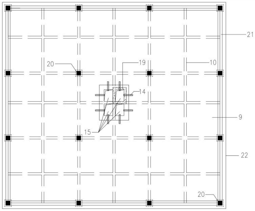
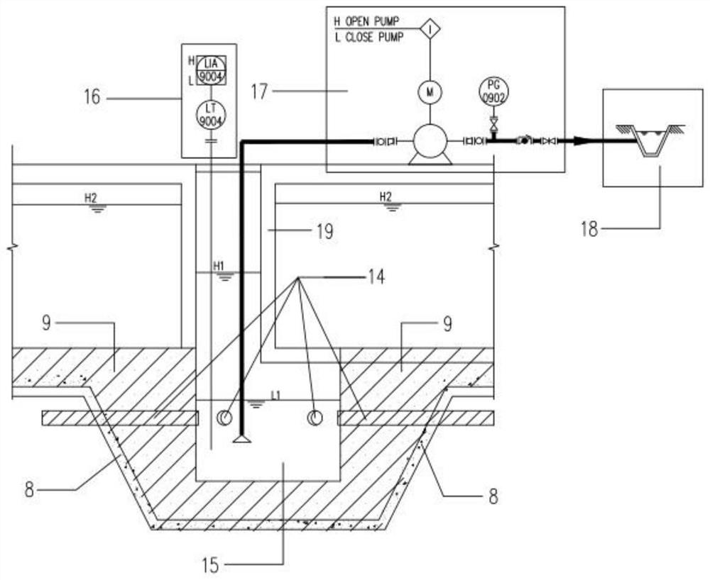
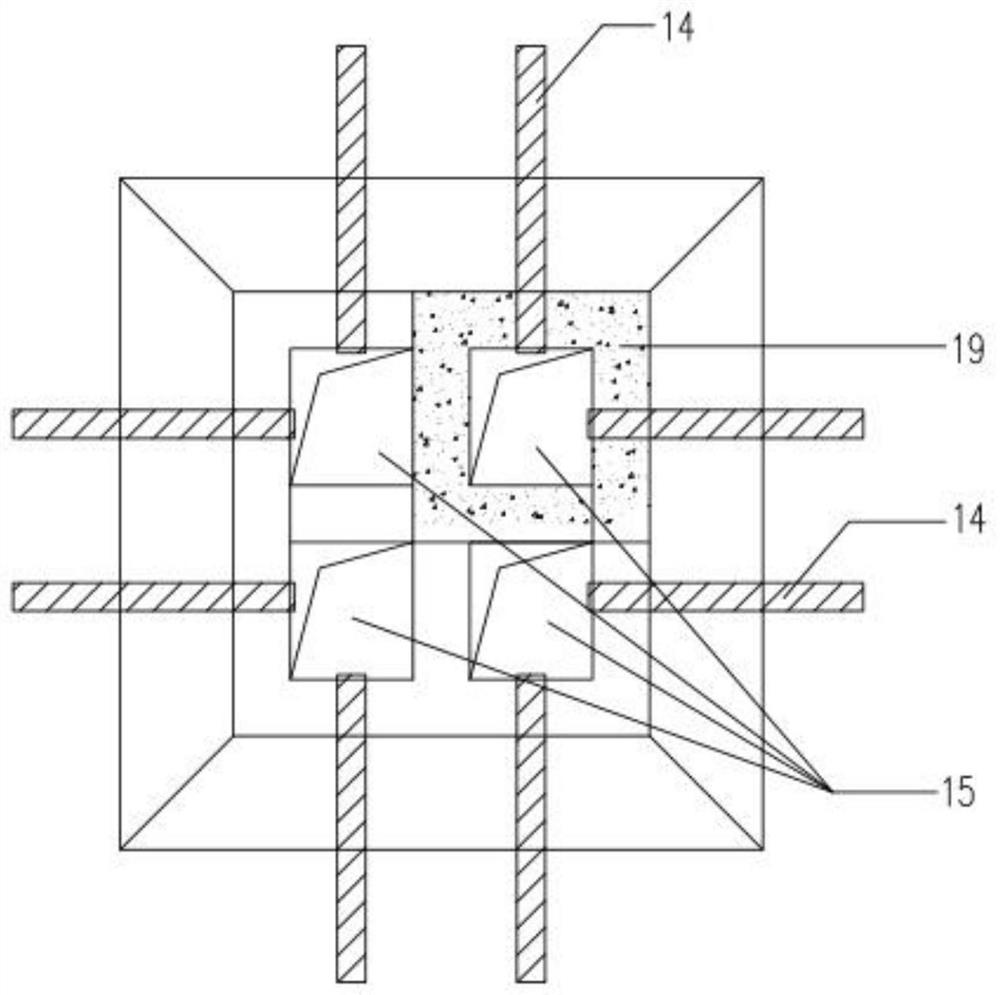
[0050] Such as Figure 1-5 As shown, the underground anti-floating pool for water release and pressure reduction is equipped with a composite filter layer at the bottom of the pool. Sand layer 3, second filter layer - medium coarse sand layer 4, non-woven geotextile 5, third filter layer - gravel layer 6, polyethylene color strip cloth 7, pool plain concrete cushion 8, pool Reinforced concrete floor 9. Except that the protected impermeable soil layer 1, the plain concrete cushion layer 8 of the pool, and the reinforced concrete bottom plate 9 of the pool are the original soil layer or the pool structure body, the other layers are specific components of the composite reverse filter layer.

[0051]Among them, the first layer of reverse filter layer - fine sand layer 3 and the second layer of reverse filter layer - medium coarse sand layer 4 are collectively ...


PUM

PropertyMeasurementUnit
thicknessaaaaaaaaaa

Abstract

The invention discloses an underground anti-floating pool for water drainage and pressure reduction. The underground anti-floating pool comprises a pool, a water collecting pit is arranged in the pool and located below a pool reinforced concrete bottom plate, a monitoring well communicated with the water collecting pit is arranged above the water collecting pit, the top elevation of the monitoring well is larger than or equal to the elevation of the pool, and it is guaranteed that the pool and the monitoring well are isolated from each other; a composite inverted filter layer is arranged at the bottom of the pool reinforced concrete bottom plate, a drainage pipe is arranged in the composite inverted filter layer, and the drainage pipe communicates with the water collecting pit; a liquid level regulation and control system is arranged in the monitoring well, and the liquid level in the monitoring well is automatically controlled through the liquid level regulation and control system. According to the underground anti-floating pool for water drainage and pressure reduction and a water drainage and pressure reduction method thereof, the composite inverted filter layer composed of conventional building materials is arranged at the bottom of the pool, underground water is collected and converged into the water collecting pit, the water buoyancy of a bottom plate of the pool is eliminated, and seepage water belongs to clear water, does not take away soil particles of undisturbed soil and does not pollute the environment, so that the underground anti-floating pool for water drainage and pressure reduction and the water drainage and pressure reduction method thereof belongs to an economical and environment-friendly pool anti-floating technology.

Description

technical field [0001] The invention relates to the technical field of construction engineering, in particular to an underground anti-floating water pool for releasing water and reducing pressure and an anti-floating method. Background technique [0002] Commonly used anti-float design methods for pools include pressure weight anti-float method, structural anti-float method, and anchoring anti-float method. The anti-float design of the pool is safe by increasing the structural counterweight or increasing the anti-lift bearing capacity. [0003] Pressure weight anti-float method: Anti-floating pressure heavy load includes the self-weight of the bottom plate of the underground structure and its upper part, the self-weight of the structural plate picked out from the bottom plate of the underground structure and the self-weight of the upper covering soil, the self-weight of the upper part of the underground structure or the anti-floating provided by the top pressure structure ca...

Claims


Application Information

Patent Timeline
Patent Type & Authority Applications(China)
IPC IPC(8): E03F5/10E02D31/12B32B33/00B32B9/02B32B9/04B32B5/16B32B5/30B32B5/02B32B9/00B32B27/32B32B27/06G05D9/12
CPCE03F5/10E02D31/12B32B33/00B32B9/02B32B9/002B32B9/045B32B9/047B32B9/04B32B9/048B32B5/16B32B5/30B32B5/02B32B9/00B32B27/32B32B27/06G05D9/12
Inventor 张瑞松朱翔骆敏
Owner 浙江省天正设计工程有限公司
Why Eureka
Try Eureka