
Full-automatic glass tube iron wire strapping machine

A glass tube and strapping machine technology, which is applied to the parts of strapping machinery, strapping materials, packaging automatic control, etc., can solve the problems of manpower and material resources for strapping glass tubes, low added value of glass tubes, and sharp edge damage. Achieve the effects of reducing labor intensity, light weight and long service life

Pending Publication Date: 2021-11-30
武汉科拉欧德机械科技有限公司
View PDF0 Cites 0 Cited by
  • Summary
  • Abstract
  • Description
  • Claims
  • Application Information

AI Technical Summary

Problems solved by technology

[0002] At present, there are many manufacturers of glass tubes in the market, because glass tubes need to continuously melt and purify the raw materials at high temperature, so in general, glass tube manufacturers will continue to produce glass tubes throughout the year in order to avoid shutdown, and at the same time, the production speed of glass tubes is very fast , but because the temperature of the glass tube is very high when it is first produced, it cannot be bundled manually. If it takes a long time, it will cause material storage. If there is too much backlog, it will cause the glass tube to break and cause certain economic losses. Human and material resources, and even cause damage because of the sharp edge, the loss outweighs the gain
[0003] The existing binding machines on the market include soft rope binding machines and steel belt binding machines. Because the added value of the glass tube itself is not high, the cost of binding the glass tubes with the steel belt binding machine will increase significantly, and the gain outweighs the gain. Because the high temperature of the glass tube is scalded, it will cause unnecessary troubles for storage and transportation

Method used


Image

  • Full-automatic glass tube iron wire strapping machine
  • Full-automatic glass tube iron wire strapping machine
  • Full-automatic glass tube iron wire strapping machine

Examples


Embodiment Construction

[0027] The present invention will be further described below in conjunction with the accompanying drawings. It should be noted that this embodiment is based on the technical solution, and provides detailed implementation and specific operation process, but the protection scope of the present invention is not limited to the present invention. Example.

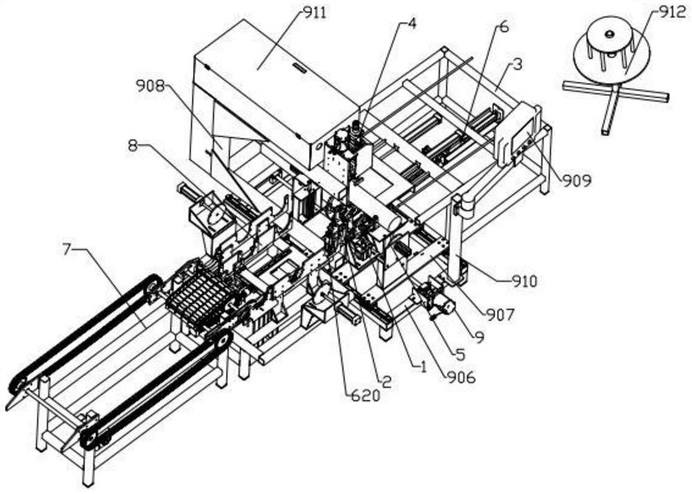
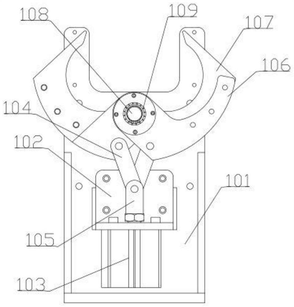
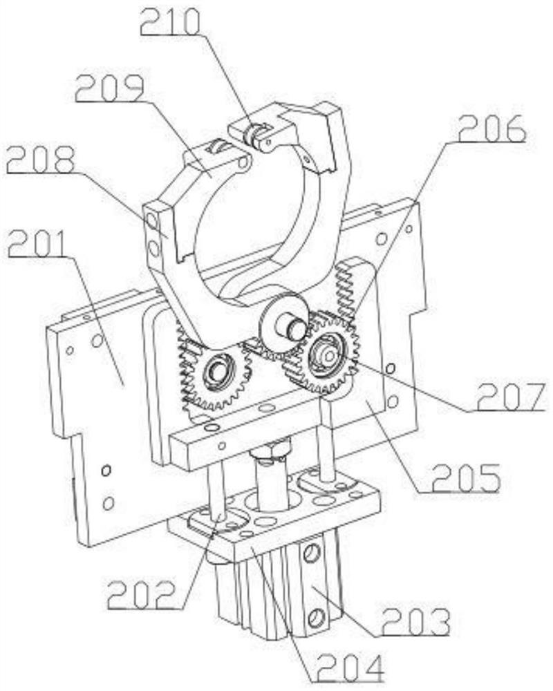
[0028] A fully automatic glass tube iron wire binding machine, characterized in that: a fully automatic glass tube iron wire binding machine, the body is sequentially provided with a chain feeding system 7, a feeding system 8, a wire feeding and cutting system 6, and a base along the workpiece transmission direction Sliding table system 9 and blanking system 3, on the base sliding table system 9, screw moving system, alignment system, tube holding system 1, wire holding system 2, and wire twisting system 4 are arranged in sequence parallel to the direction of the workpiece. The wire holding system 4 is located directly above the...


PUM


Abstract

The invention discloses a full-automatic glass tube iron wire strapping machine. The machine is characterized in that a chain feeding system, a feeding system, a wire feeding and cutting system, a base sliding table system and a discharging system are sequentially arranged on a machine body in the workpiece conveying direction; a lead screw moving system, alignment systems, tube holding systems, a wire holding system and a wire twisting system are sequentially arranged on the base sliding table system in the direction parallel to a workpiece; the wire twisting system is located over the tube holding systems and the wire holding system; the two tube holding systems are arranged; the wire holding system is located between the two tube holding systems; and the two alignment systems are located at the two ends of the base sliding table system respectively. By the adoption of the structure, the problem that an existing glass tube is not prone to strapping due to overheating and over-high brittleness can be solved, meanwhile, the broken glass tube can be prevented from hurting the human body during strapping, manpower is liberated, the human body is protected, and the working efficiency is improved.

Description

technical field [0001] The invention belongs to the technical field of binding machines, in particular to an automatic glass tube iron wire binding machine. Background technique [0002] At present, there are many manufacturers of glass tubes in the market, because glass tubes need to continuously melt and purify the raw materials at high temperature, so in general, glass tube manufacturers will continue to produce glass tubes throughout the year in order to avoid shutdown, and at the same time, the production speed of glass tubes is very fast , but because the temperature of the glass tube is very high when it is first produced, it cannot be bundled manually. If it takes a long time, it will cause material storage. If there is too much backlog, it will cause the glass tube to break and cause certain economic losses. Human and material resources, and even cause damage due to sharp edges, the loss outweighs the gain. [0003] The existing binding machines on the market inclu...

Claims


Application Information

Patent Timeline
Patent Type & Authority Applications(China)
IPC IPC(8): B65B13/16B65B13/20B65B13/28B65B13/18B65B35/24B65B57/20B65B19/34
CPCB65B13/16B65B13/20B65B13/28B65B13/18B65B35/24B65B57/20B65B19/34
Inventor 隋振
Owner 武汉科拉欧德机械科技有限公司
Learn More