Supercharge Your Innovation With Domain-Expert AI Agents!

Novel heat pipe type liquid cooling cold plate

A liquid-cooled cold plate and heat pipe technology, applied in indirect heat exchangers, lighting and heating equipment, electrical components, etc., can solve problems such as design stranding, improve service life, improve heat uniformity, and save computing costs Effect

Pending Publication Date: 2021-11-30
上海热普电子科技有限公司
View PDF0 Cites 1 Cited by
  • Summary
  • Abstract
  • Description
  • Claims
  • Application Information

AI Technical Summary

Problems solved by technology

This is almost the limit of the cold plate design in the industry at present. If you want to reduce the cost of materials and connect two CPUs in series without lowering the temperature of the inlet water, the design will inevitably run aground.

Method used


Image

  • Novel heat pipe type liquid cooling cold plate
  • Novel heat pipe type liquid cooling cold plate

Examples


Embodiment 1

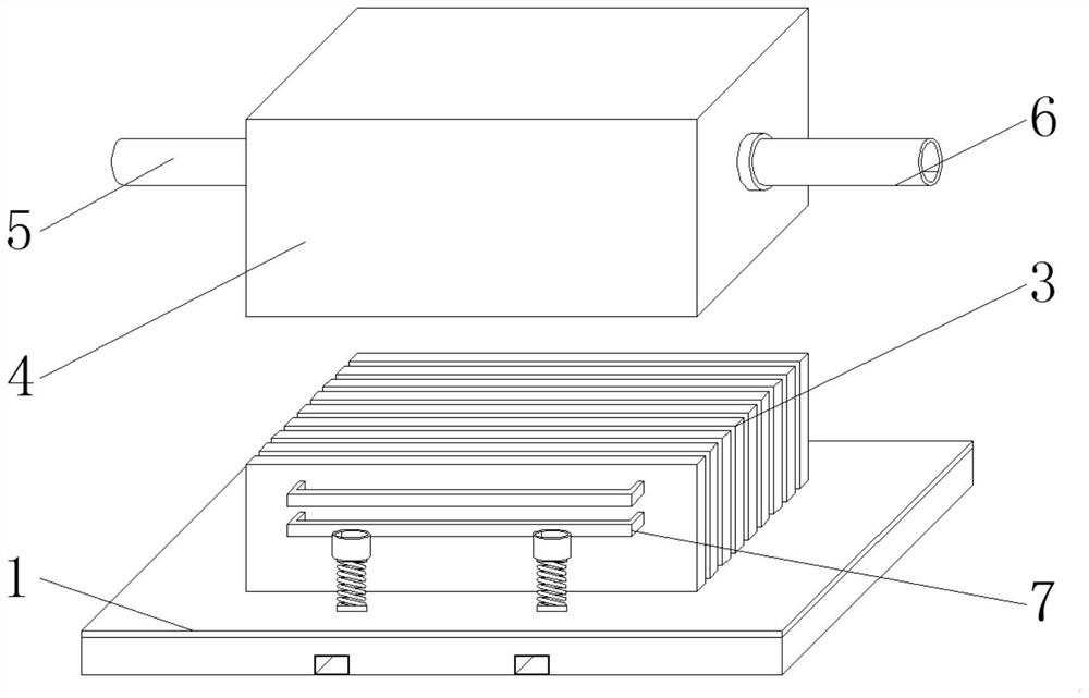
[0018] Such as figure 1 As shown, the present invention provides a technical solution: a novel heat pipe type liquid-cooled cold plate, including a base evaporation chamber 1, a plurality of fins 3 are fixedly connected to the upper surface of the base evaporation chamber 1, and the frontmost fin 3 The front surface is fixedly connected with a plurality of heat pipes 7, the rear ends of the heat pipes 7 run through a plurality of fins 3, and communicate with the base evaporation chamber 1, the base evaporation chamber 1 is provided with a cold plate cover 4, and the left side of the cold plate cover 4 The water inlet pipe 5 and the water outlet pipe 6 are respectively connected to the side and the right side. The base evaporation chamber 1 can use either copper nickel-plated heat pipes or aluminum heat pipes. The fins 3 are made of aluminum, and an aluminum cold plate cover 4 is welded on the outside. , the water inlet pipe 5 and the water outlet pipe 6 can keep the tank desig...

Embodiment 2

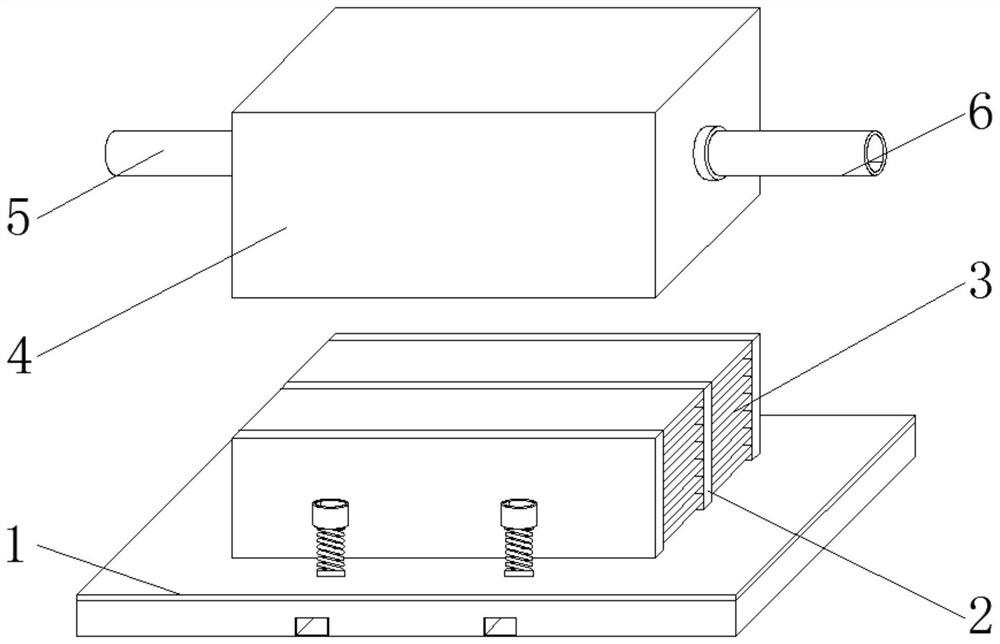
[0020] Such as figure 2 As shown, the present invention provides a technical solution: a novel heat pipe type liquid-cooled cold plate, including a base evaporation chamber 1, the upper surface of the base evaporation chamber 1 is fixedly connected with a plurality of evaporation chamber vertical pipes 2, and the evaporation chamber vertical pipes 2 The bottom of the base is connected to the inside of the base evaporation chamber 1, and a plurality of fins 3 are fixedly connected between two adjacent evaporation chamber vertical pipes 2. A cold plate cover 4 is provided above the base evaporation chamber 1, and a cold plate cover 4 The left side and the right side are respectively connected with the water inlet pipe 5 and the water outlet pipe 6. The heat source of the base evaporation chamber 1 uses the latent heat of boiling and vaporization of the working fluid to quickly transfer the heat to the vertical pipe 2 of the three-dimensional evaporation chamber, and then the hea...


PUM


Abstract

The invention relates to the technical field of chip heat dissipation, and discloses a novel heat pipe type liquid cooling cold plate. The plate comprises a base evaporation cavity, a plurality of fins are fixedly connected to the upper surface of the base evaporation cavity, a cold plate cover is arranged above the base evaporation cavity, and the left side and the right side of the cold plate cover communicate with a water inlet pipe and a water outlet pipe respectively. The cold plate has a remote heat transfer capability, compared with a common relieved tooth copper (aluminum) cold plate and a heat pipe cold plate type radiator, the heat pipe cold plate radiator has the advantages that the height of the fins can be increased to a great extent, the soaking performance of the fins is improved, the effective heat exchange area of the radiator is increased, the number of the fins can be reduced, the flow resistance of the cold plate can be reduced through the sparse design, design and manufacturing are easy, as long as a sealing cover is additionally arranged above an original air-cooled heat pipe radiator, the novel heat pipe type liquid cooling cold plate can be designed, and the novel heat pipe type liquid cooling cold plate is formed at a time through a copper brazing or aluminum brazing welding process.

Description

technical field [0001] The invention relates to the technical field of chip heat dissipation, in particular to a novel heat pipe type liquid-cooled cold plate. Background technique [0002] At present, the mainstream chip design is iteratively updated quickly, with increasingly multi-core and high frequency. The requirements for heat dissipation design are becoming more and more stringent. High TDP (Thermal Design Power), high heat flux density, and lower temperature control requirements are like three mountains, pressing on the head of heat dissipation designers. With the latest generation of Intel CPU, Eagle Stream For example, the TDP is 350W, but the surface temperature of the CPU is required to be controlled at no higher than 55°C. It is obviously impossible to use traditional air cooling for heat dissipation. And as China and the world release relevant policies on carbon emissions and carbon neutrality, data centers are required to save energy, control power usage eff...

Claims


Application Information

Patent Timeline
Patent Type & Authority Applications(China)
IPC IPC(8): F28D15/02H01L23/367H01L23/427
CPCF28D15/02H01L23/367H01L23/427
Inventor 王亚君赵建国
Owner 上海热普电子科技有限公司
Features
  • R&D
  • Intellectual Property
  • Life Sciences
  • Materials
  • Tech Scout
  • Unparalleled Data Quality
  • Higher Quality Content
  • 60% Fewer Hallucinations
Learn More