Thermal management control method and system and fuel cell vehicle

A control system and control method technology, applied in the direction of power system fuel cells, fuel cells, fuel cell additives, etc., can solve the problems of impractical thermal management control methods and systems, large workload of cooling fans, low energy utilization, etc. , to optimize the configuration of the thermal management control system, improve the level of thermal management, and ensure efficient utilization

Pending Publication Date: 2021-11-30
BEIJING SINOHYTEC
View PDF0 Cites 5 Cited by
  • Summary
  • Abstract
  • Description
  • Claims
  • Application Information

AI Technical Summary

Problems solved by technology

Among them, the temperature rise of the coolant in the vehicle heating system depends entirely on the PTC heater, which consumes a lot of energy; while the high-power fuel cell has high power output, the working temperature can be as high as 70-80°C, and the temperature difference between the engine inlet and outlet must be maintained at 10°C Within the limit, this part of the heat is dissipated through the radiator and is not used in the vehicle heating system, resulting in waste of heat and low energy utilization; in addition, when the cooling system of the hydrogen fuel cell engine is working, the cooling fan has a large workload, consumes a lot of energy, and makes noise larger
At present, although attempts have been made to develop a technical solution for heating the whole vehicle by using the waste heat of fuel cells, based on the current supply status of domestic fuel cell engines and vehicle manufacturers, there is no practical and compatible thermal management control method and system

Method used


Image

  • Thermal management control method and system and fuel cell vehicle
  • Thermal management control method and system and fuel cell vehicle
  • Thermal management control method and system and fuel cell vehicle

Examples


Embodiment 1

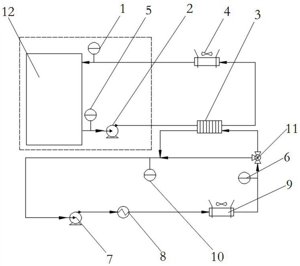
[0042] This embodiment provides a thermal management method, see attached figure 1 Attach figure 2 Attachmentimage 3 The thermal management control method includes:

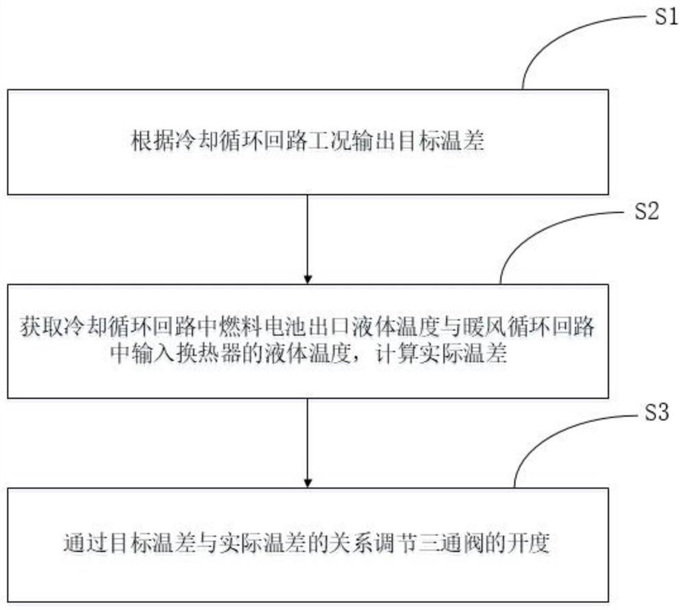
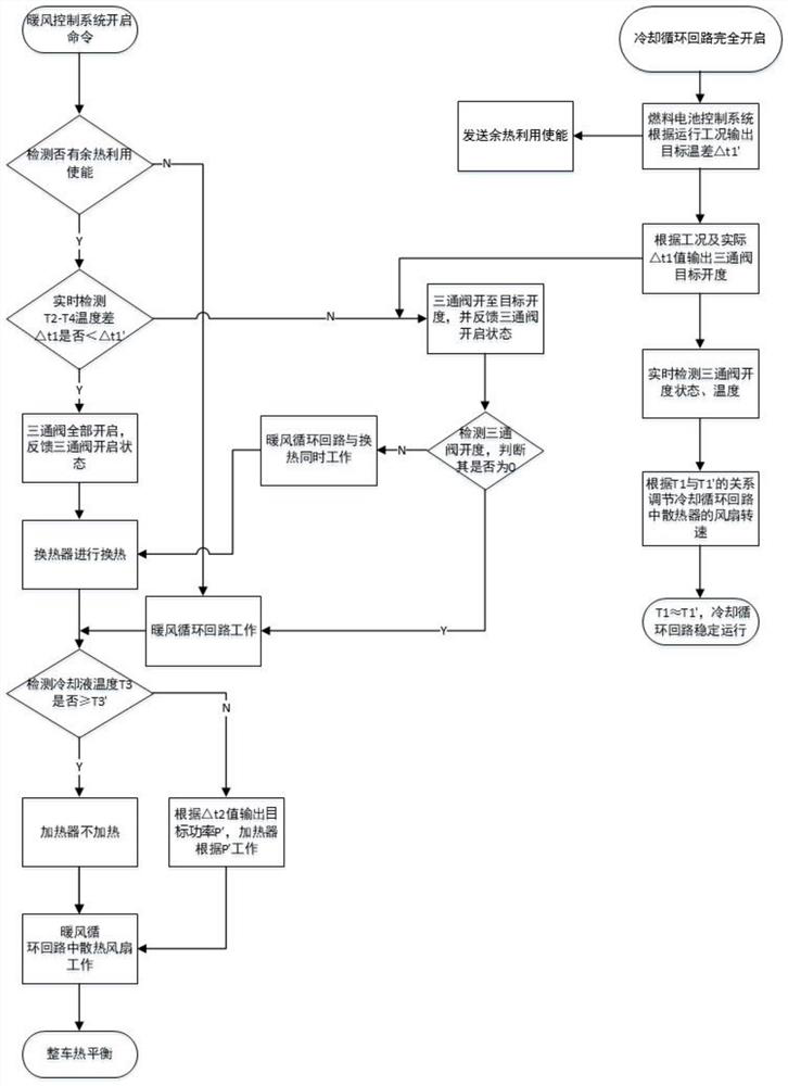
[0043] The heat exchange of the cooling cycle loop and the cooling cycle loop is adjusted by the heat transfer loop. The heat exchange circuit and the cooling circulation circuit are heat exchange by the heat exchanger 3; the heat transfer circuit and the warm air circulation are controlled by the three-way valve 11. Circuit connection;

[0044] According to the temperature parameter relationship of the cooling cycle loop and the warm air circulation loop, the liquid flow in the line of the heat transfer circuit and the heating loop is adjusted.

[0045] In the present embodiment, three heat dissipation circulation circuits are included, and the cooling cycle circuit is used to cool the fuel cell stack, and the other is that the warm air circulation circuit is used to provide warm air to the whole vehicle; the third ...

Embodiment 2

[0075] Based on the same inventive concept, the embodiment of the present invention also provides a thermal management control system, and since the principle of the problem solving the heat management control system is similar to the thermal management control method of the foregoing embodiment, the implementation of the present embodiment can see the aforementioned heat The implementation of the management control method is not repeated.

[0076] This embodiment provides a thermal management control system including a cooling circulation loop, a warm cycle circuit and a heat transfer circuit; the heat transfer circuit and the cooling cycle circuit achieve heat exchange by heat exchanger 3; The heat transfer circuit and the heating circulation circuit pass through the opening degree of the tube in the pipeline;

[0077] The thermal management control system controls the three-way valve opening according to the temperature parameter relationship of the cooling cycle loop and the w...

Embodiment 3

[0094] Based on the same inventive concept, the embodiment of the present invention further provides a fuel cell vehicle, since the principle of the problem solving the fuel cell vehicle is similar to the thermal management control system of the foregoing embodiment, so the implementation of the present embodiment can see the aforementioned thermal management The implementation of the control system is not repeated.

[0095] Embodiments of the present invention provide a fuel cell vehicle including a thermal management control system of a fuel cell vehicle as described in any embodiment.

[0096] In the present embodiment, the warm air circulation loop can be controlled by the vehicle hot air system, and the cooling cycle circuit is controlled by the fuel cell system, and the thermal management control of the vehicle is achieved through the interaction of the vehicle hot air system and the fuel cell system.

[0097] In the embodiment of the present invention, a tube-shell heat exc...


PUM


Abstract

The invention relates to the field of fuel cell vehicles, in particular to a thermal management control method and system and a fuel cell vehicle. The method comprises the steps: adjusting the heat exchange between a cooling circulation loop and a warm air circulation loop through a heat exchange loop, wherein heat exchange is conducted between the heat exchange loop and the cooling circulation loop through a heat exchanger; controlling the heat exchange loop to be communicated with the warm air circulation loop through a three-way valve; controlling the opening degree of the three-way valve according to the temperature parameter relation of the cooling circulation loop and the warm air circulation loop, and adjusting the liquid flow in the pipeline of the heat exchange loop and the warm air circulation loop. According to the embodiment of the invention, the heat dissipated when the fuel cell works is transferred to the warm air circulation loop, and the opening degree of the three-way valve in the warm air circulation loop is adjusted according to the temperature parameters of different loops, so that the temperature in a whole vehicle cabin and the temperature of the fuel cell can be accurately controlled under the condition of high-power operation of the fuel cell; moreover, the efficient utilization of waste heat can be ensured under the conditions that the fuel cell runs at low power and the available waste heat quantity is smaller.

Description

Technical field [0001] The present invention relates to the field of fuel cell vehicles, and more particularly to a thermal management control method, a system, and a fuel cell vehicle. Background technique [0002] In the field of new energy vehicles, the fuel cell system has the advantages of non-polluting, short hydrogenation time, long renewal mumens, and strong environmental adaptability, and has broad application scenarios. However, as the vehicle's power demand is getting bigger, high-power fuel cell engine is gradually applied to new energy vehicles; the fuel cell engine system is high power output, and fuel cell vehicles face a big challenge in thermal management and battery life. Fuel battery vehicles have no traditional engine heat, requires simple use of PTC heaters, consumes a lot of electricity in winter, such as a 12-meter bus for the PTC power consumption of 10 hours to 15 ~ 20KWh; while fuel cell About 50% of the heat is scattered by a cooling fan, such as the he...

Claims


Application Information

Patent Timeline
Patent Type & Authority Applications(China)
IPC IPC(8): H01M8/04007H01M8/04029H01M8/0432H01M8/04746B60L58/33B60L58/34
CPCH01M8/04074H01M8/04029H01M8/04358H01M8/04768B60L58/33B60L58/34H01M2250/20Y02T90/40Y02E60/50
Inventor 包书慧刘然杨绍军张禾贾能铀
Owner BEIJING SINOHYTEC
Why Eureka
Try Eureka