Supercharge Your Innovation With Domain-Expert AI Agents!

Toxic and harmful gas trapping device

A technology of harmful gas and airflow, applied in the direction of removing smoke and dust, cleaning methods and utensils, chemical instruments and methods, etc., can solve the problems of high energy consumption, low poison capture efficiency, etc. Structural design novel effect

Inactive Publication Date: 2021-12-03
CHINA PETROLEUM & CHEM CORP +1
View PDF11 Cites 0 Cited by
  • Summary
  • Abstract
  • Description
  • Claims
  • Application Information

AI Technical Summary

Problems solved by technology

[0007] In order to solve the technical problems of low efficiency and high energy consumption of poisonous substances dissipated from existing multi-leakage points and large-volume equipment in the existing local upper ventilation hood, the present invention discloses a toxic and harmful gas trapping device

Method used


Image

  • Toxic and harmful gas trapping device
  • Toxic and harmful gas trapping device

Examples


Embodiment 1

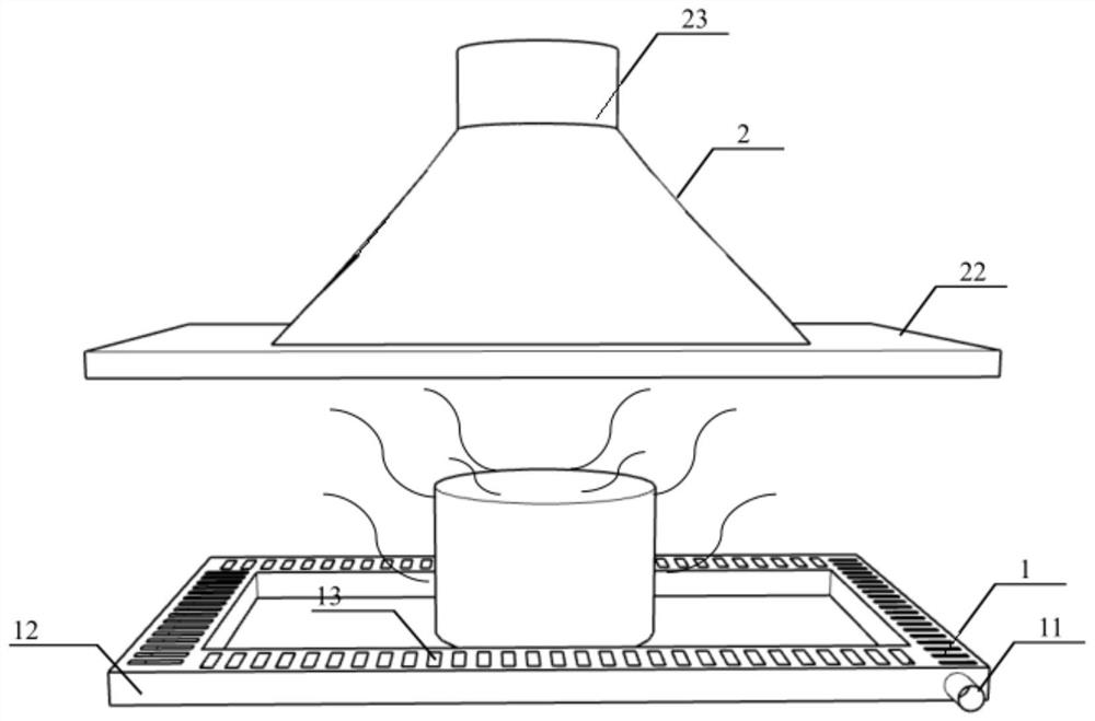
[0030] Such as figure 1 and 2 As shown, a toxic and harmful gas trapping device includes an exhaust body 2 and an air supply body 1 arranged up and down oppositely, wherein the air supply body 1 is arranged upwards for blowing toxic and harmful gases upwards, and the exhaust body 2 It is installed downwards to collect toxic and harmful gases and discharge them from the exhaust pipe on the top. Between the above-mentioned exhaust body 2 and air supply body 1, the air supply and exhaust air flow forms a stable environment surrounding the production equipment where toxic and harmful gases leak. Blow air.

[0031] In particular, the air supply body 1 includes an air inlet pipe 11, an air supply hood 12 and an air supply port 13, the air inlet pipe 11 is fixedly connected with the air supply hood 12, and 68 uniformly arranged on the upper surface of the above-mentioned air supply hood 12 Air supply port 13.

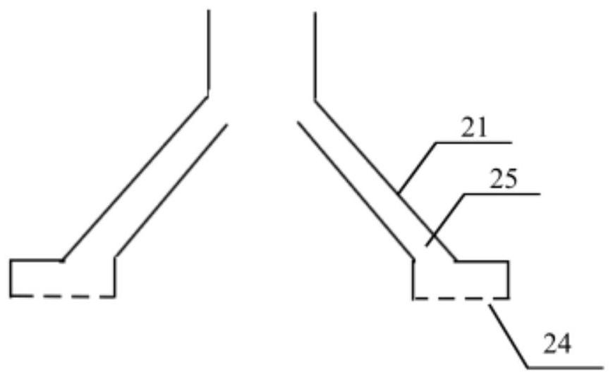
[0032] In particular, the above-mentioned air supply hood 12 is a circ...

Embodiment 2

[0046] Such as figure 1 and 2 As shown, a toxic and harmful gas trapping device includes an exhaust body 2 and an air supply body 1 arranged up and down oppositely, wherein the air supply body 1 is arranged upwards for blowing toxic and harmful gases upwards, and the exhaust body 2 It is installed downwards to collect toxic and harmful gases and discharge them from the exhaust pipe on the top. Between the above-mentioned exhaust body 2 and air supply body 1, the air supply and exhaust air flow forms a stable environment surrounding the production equipment where toxic and harmful gases leak. Blow air.

[0047] In particular, the air supply body 1 includes an air inlet pipe 11, an air supply cover 12 and an air supply port 13, the air intake pipe 11 is fixedly connected with the air supply cover 12, and 56 pieces are evenly arranged on the upper surface of the above-mentioned air supply cover 12. Air supply port 13.

[0048] In particular, the above-mentioned blower hood 12 ...


PUM


Abstract

The invention discloses a toxic and harmful gas trapping device, and relates to the technical field of toxic and harmful gas collection. The toxic and harmful gas trapping device comprises an air exhaust body and an air supply body which are oppositely arranged up and down, wherein the air supply body is arranged upwards and is used for blowing toxic and harmful gas upwards; the air exhaust body is arranged downwards and is used for collecting the toxic and harmful gas and exhausting the toxic and harmful gas from an air exhaust pipe at the top; and stable blowing and sucking airflow surrounding toxic and harmful gas leakage production equipment is formed between the air exhaust body and the air supply body through air supply and air exhaust airflow. The toxic and harmful gas trapping device has the beneficial effects that a lower air supply cover and an upper air exhaust cover are combined, and the stable blowing and sucking airflow formed by the lower air supply cover and the upper air exhaust cover effectively traps dissipated toxic and harmful substances, so that the dissipation range of the toxic and harmful substances is small, the trapping efficiency can reach 90%, and control and efficient trapping of the toxic and harmful gas dissipated by multi-leakage-point and large-size equipment are realized; and compared with a traditional local umbrella-shaped upper ventilation cover, the energy consumption is reduced by 30% or above under the same or similar effect, and the energy consumption is greatly reduced.

Description

technical field [0001] The invention relates to the technical field of collecting toxic and harmful gases, in particular to a toxic and harmful gas collecting device. Background technique [0002] Toxic gas is a gaseous or highly volatile toxic chemical under normal temperature and pressure. It comes from industrial pollution, coal and petroleum combustion, and the decomposition of biological materials. It has a stimulating effect on the respiratory tract and is easy to be inhaled and poisoned. Including ammonia, ozone, nitrogen dioxide, sulfur dioxide, carbon monoxide, carbon dioxide, hydrogen sulfide and photochemical smog. [0003] There are many ways to deal with toxic gases, mainly including chemical and physical methods. The chemical method is to react the toxic gas with other chemicals, and the toxic gas after the reaction is either non-toxic or becomes a solid substance. The non-toxic gas can avoid harm to the human body, and the solid matter can be conveniently co...

Claims


Application Information

Patent Timeline
Patent Type & Authority Applications(China)
IPC IPC(8): B08B15/04
CPCB08B15/04
Inventor 于金宁武珊珊张昌运刘波赵盛何春宏孔飞
Owner CHINA PETROLEUM & CHEM CORP
Features
  • R&D
  • Intellectual Property
  • Life Sciences
  • Materials
  • Tech Scout
  • Unparalleled Data Quality
  • Higher Quality Content
  • 60% Fewer Hallucinations
Learn More