Low-temperature-resistant butterfly valve body and production process thereof

A production process and low temperature resistance technology, applied in the field of valve manufacturing, can solve the problem that the butterfly valve body cannot have both low temperature resistance and sealing performance, so as to avoid the diffusion and circulation of heat, improve the low temperature resistance, and improve the low temperature resistance. Effect

Active Publication Date: 2021-12-03
JIANGSU RUIHONG MASCH CO LTD
View PDF6 Cites 0 Cited by
  • Summary
  • Abstract
  • Description
  • Claims
  • Application Information

AI Technical Summary

Problems solved by technology

[0004] The object of the present invention is to provide a low temperature resistant butterfly valve body and its production process, which is used to solve the problem that the butterfly valve body in the prior art cannot have good low temperature resistance and sealing performance, and the upper valve shaft seat and the lower valve shaft seat The end face grinding and drilling efficiency needs to be improved to further improve the processing efficiency and processing accuracy of the butterfly valve body.

Method used


Image

  • Low-temperature-resistant butterfly valve body and production process thereof
  • Low-temperature-resistant butterfly valve body and production process thereof
  • Low-temperature-resistant butterfly valve body and production process thereof

Examples


Embodiment 1

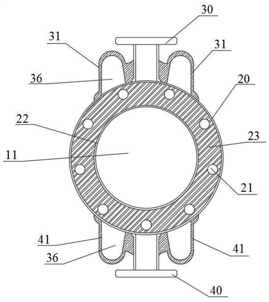
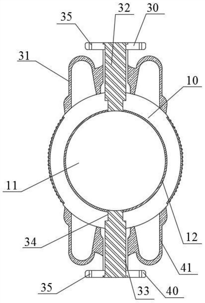
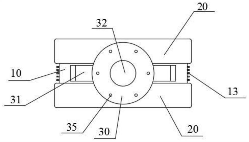
[0039] Such as Figure 1-4 As shown, this embodiment provides a low temperature resistant butterfly valve body, including a valve body body 10, flanges 20 are provided at both ends of the valve body body 10, and a center of the valve body body 10 and the flange 20 is provided with a Fluid channel 11; the top and bottom of the valve body main body 10 are located between the flanges 20 on both sides and are respectively provided with an upper valve shaft seat 30 and a lower valve shaft seat 40, and the two sides of the upper valve shaft seat 30 are arranged symmetrically with the valve body. The upper valve neck 31 of the main body 10 is integrally formed, and the lower valve neck 41 integrally formed with the valve body main body 10 is symmetrically provided on both sides of the lower valve shaft seat 40; The outer wall of 10 is provided with outer low temperature resistant structure.

[0040] The low temperature resistant butterfly valve body of this embodiment is improved on...

Embodiment 2

[0047] Such as Figure 5-6 As shown, the present embodiment provides a conveniently adjustable grinding and drilling equipment for butterfly valve body processing, including a frame 100, the upper sides of the frame 100 are respectively provided with a grinding mechanism 200, a drilling mechanism 300, and the grinding mechanism 200 and A clamping mechanism 400 is provided between the drilling mechanism 300; the grinding mechanism 200 is used to grind the end faces of the upper valve shaft seat 30 and the lower valve shaft seat 40 of the valve body body 10; The end faces of the seat 30 and the lower valve shaft seat 40 are drilled to obtain an end face hole 35; the clamping mechanism 400 is used to clamp the valve body main body 10 and perform position adjustment.

[0048] The grinding and drilling equipment clamps the valve body body 10 through the grinding mechanism 200, the drilling mechanism 300, and the clamping mechanism 400, and grinds the end faces of the upper valve sh...

Embodiment 3

[0060] Such as Figure 1-9 As shown, the present embodiment provides a production process of a low temperature resistant butterfly valve body, comprising the following steps:

[0061]The casting mold is made to have the same shape as the butterfly valve body with the valve body main body 10, the flange 20, the upper valve shaft seat 30, the lower valve shaft seat 40, the upper valve neck 31, and the lower valve neck 41, and place it with the fluid channel 11 , the center cavity 32, and the sand core with the same size as the gripping hole 36, the molten steel is poured into the casting mold through the ladle to obtain the valve body casting; wherein, the sand core is added by 94wt% to 96wt% of the original sand according to the weight ratio Prepared from 4wt%-6wt% water glass; the casting temperature is 1520-1540°C;

[0062] When the temperature of the casting mold is lowered to 920-980°C, the sand core is cleaned, the outer surface of the valve body body 10 and the flange 20...


PUM


Abstract

The invention discloses a low-temperature-resistant butterfly valve body and a production process thereof, and relates to the technical field of valve manufacturing. The butterfly valve body comprises a valve body main body, flange plates are arranged at the two ends of the valve body main body, and a fluid channel penetrates through the centers of the valve body main body and the flange plates; an upper valve shaft seat and a lower valve shaft seat are arranged above and below the valve body main body and located between the flange plates on the two sides respectively, upper valve necks integrally formed with the valve body main body are symmetrically arranged on the two sides of the upper valve shaft seat, and lower valve necks integrally formed with the valve body main body are symmetrically arranged on the two sides of the lower valve shaft seat; and an inner low-temperature-resistant structure is arranged on the inner wall of the valve body main body, and an outer low-temperature-resistant structure is arranged on the outer wall of the valve body main body. The butterfly valve body keeps good low-temperature resistance and keeps good sealing performance after being assembled with a butterfly plate and a valve shaft, in the production process, grinding and drilling equipment integrates the functions of grinding, drilling and position adjusting, grinding and drilling can be conducted synchronously, and the machining efficiency and machining precision of the butterfly valve body are improved.

Description

technical field [0001] The invention relates to the technical field of valve manufacturing, in particular to a low-temperature-resistant butterfly valve body and a production process thereof. Background technique [0002] Butterfly valve, also known as flap valve, is a regulating valve with simple structure. The closing part (disc or butterfly plate) is a disc, which rotates around the valve shaft to achieve opening and closing. Butterfly valve has simple structure and small size. , light weight, low material consumption, small installation size, fast switching, 90° reciprocating rotation, small driving torque, etc., used to cut off, connect, and adjust the medium in the pipeline, with good fluid control characteristics and closed seal Performance, in order to meet the requirements of high and low temperature, strong erosion, long life and other industrial applications, the metal sealing butterfly valve has been greatly developed; [0003] The invention patent with applicat...

Claims


Application Information

Patent Timeline
Patent Type & Authority Applications(China)
IPC IPC(8): F16K1/22F16K1/226F16K27/02B22C9/02B22C9/22B23P15/00
CPCF16K1/22F16K27/0218F16K1/226B22C9/22B22C9/02B23P15/001
Inventor 郭云章
Owner JIANGSU RUIHONG MASCH CO LTD
Why Eureka
Try Eureka