3D printing porous interbody fusion cage

An intervertebral fusion cage and 3D printing technology, applied in the field of medical devices, can solve problems such as stress shielding and high elastic modulus, and achieve the effects of improving stability, improving mechanical strength, reducing displacement and even prolapse

Pending Publication Date: 2021-12-07
湖南华翔医疗科技有限公司
View PDF0 Cites 2 Cited by
  • Summary
  • Abstract
  • Description
  • Claims
  • Application Information

AI Technical Summary

Problems solved by technology

[0005] The present invention aims to solve the above-mentioned technical problems to a certain extent, and provides a 3D printed porous intervertebral fusion device, which can solve the problem of the traditional intervertebral fusion device with too high elastic modulus and the "stress shielding" effect, so that the intervertebral fusion The elastic modulus of the fusion cage is as close as possible to the elastic modulus of human bone in the patient's part

Method used


Image

  • 3D printing porous interbody fusion cage
  • 3D printing porous interbody fusion cage
  • 3D printing porous interbody fusion cage

Examples


Embodiment 1

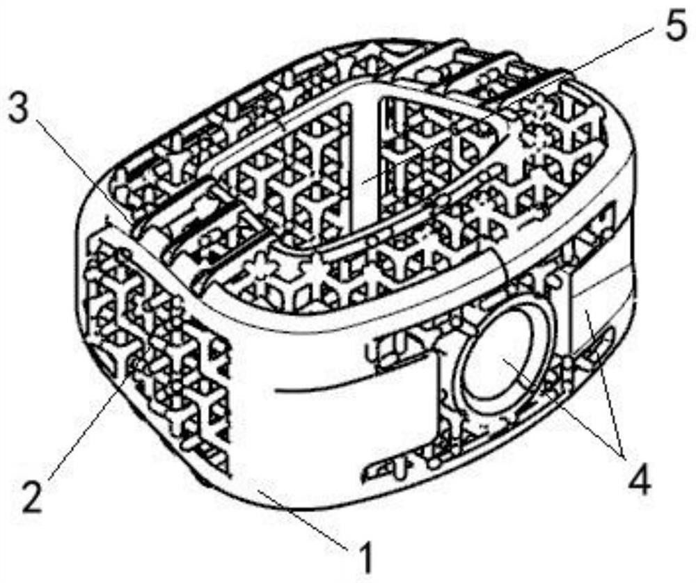
[0044] Such as Figure 1-5 Shown is a 3D printed porous intervertebral fusion device described in this embodiment, including a solid frame 1, a porous structure 2, occlusal teeth 3, a clamping mouth 4, and a bone graft chamber 5; the porous structure 2 is uniform It is filled inside the solid frame 1, so that the sides of the solid frame 1 are hollowed out, and the solid frame 1 is used as the main load-bearing structure to provide sufficient strength for the intervertebral cage. Specifically, as Figure 5 As shown, the interior or surface of the porous structure 2 is also provided with support beams 6; the upper and lower end faces of the solid frame 1 are respectively provided with a plurality of the occlusal teeth 3, and the occlusal teeth 3 arranged on the same side end faces of the solid frame 1 are arranged symmetrically. , the occlusal teeth 3 bite into the patient's spinal endplate to maintain the stability of the intervertebral fusion device; the solid frame 1 is provid...

Embodiment 2

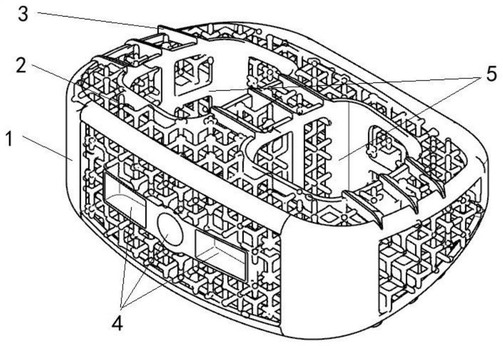
[0055] Such as figure 2 As shown, the difference between this embodiment and Embodiment 1 is that two bone graft bins 5 juxtaposed are designed on the porous type intervertebral fusion device, and the design of multiple bone graft bins 5 can adapt to larger porous type intervertebral fusion cages. The fusion device is guaranteed not to have a solid load-bearing structure in the central region of the porous intervertebral fusion device due to the oversized design of the bone graft chamber 5, resulting in uneven support for the spine.

Embodiment 3

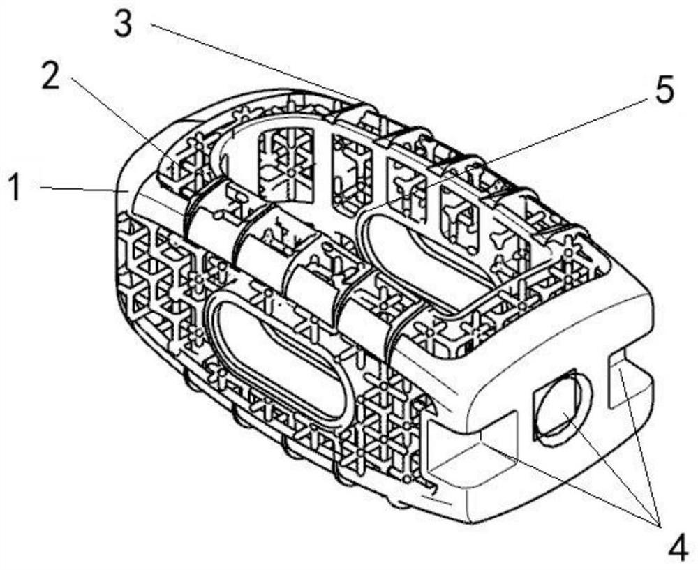
[0057] Such as image 3 As shown, the difference between this embodiment and Embodiment 1 is that the clamping port 4 is designed on the rear side of the porous intervertebral fusion device, which can be used for posterior approach surgery, while the solid frame 1 is designed as a long strip, and the doctor can Depending on the condition of the patient, only half of the intervertebral disc can be removed and a porous intervertebral fusion cage placed, or the entire intervertebral disc can be removed and two porous intervertebral fusion cages placed.


PUM

PropertyMeasurementUnit
diameteraaaaaaaaaa
pore sizeaaaaaaaaaa
porosityaaaaaaaaaa

Abstract

The invention discloses a 3D printing porous interbody fusion cage. The3D printing porous interbody fusion cage comprises a solid frame, a porous structure, meshing teeth, a clamping opening and a bone grafting bin; the porous structure is uniformly filled in the solid frame, so that each side surface of the solid frame is hollowed out; the upper end face and the lower end face of the solid frame are each provided with the plurality of meshing teeth, and the meshing teeth arranged on the end face of the same side of the solid frame are symmetrically arranged; the solid frame is provided with at least one bone grafting bin, and the bone grafting bin penetrates through the upper end face and the lower end face of the solid frame; the clamping opening is formed in the side face of the solid frame. According to the interbody fusion cage, the problems that a traditional interbody fusion cage is too high in elasticity modulus and has a stress shielding effect can be solved, and the elasticity modulus of the interbody fusion cage is close to the elasticity modulus of a human body bone of a patient part as much as possible.

Description

technical field [0001] The invention relates to the technical field of medical devices, in particular to a 3D printed porous intervertebral fusion device. Background technique [0002] Degenerative disc disease is a common disease of the human spine. Doctors usually treat patients with intervertebral fusion. Intervertebral fusion is a commonly used medical implant device for intervertebral fusion. It is placed after surgical removal of the degenerated intervertebral disc. Between two vertebral bodies, replacing part or all of the original intervertebral disc can be used to maintain the height of the patient's intervertebral body, enhance the stability of the fusion site, and increase the fusion rate between the vertebral bodies. [0003] Common intervertebral fusion cages are mainly tubular with a hollow structure in the middle, which can be filled with fragments such as autologous bone, allogeneic bone, xenograft bone or artificial bone, so as to achieve the purpose of indu...

Claims


Application Information

Patent Timeline
Patent Type & Authority Applications(China)
IPC IPC(8): A61F2/44
CPCA61F2/4455A61F2/442A61F2002/30985
Inventor 申宇邹炜民李宁向小伟王凯蒋金位郭凯旋侯凯王国华宋坤刘江
Owner 湖南华翔医疗科技有限公司
Why Eureka
Try Eureka