Permanent magnet motor direct-driven vertical mill with bidirectional load buffer device

A buffer device, vertical mill technology, applied in mechanical equipment, grain processing, spring/shock absorber, etc., can solve the problems of increasing motor power loss, low mechanical efficiency, low energy utilization rate, etc. Stable operation, convenient manufacturing and transportation, changing the effect of lengthy transmission chain

Pending Publication Date: 2021-12-07
河南全新机电设备有限公司
View PDF3 Cites 0 Cited by
  • Summary
  • Abstract
  • Description
  • Claims
  • Application Information

AI Technical Summary

Problems solved by technology

The foundation is composed of the main machine frame, the reducer base, the motor base, the anchor bolt box, the lower support of the tensioning device, etc.; the transmission device is composed of the main asynchronous motor, the main reducer, etc.; the roller plate structure, the main components are rollers and plate; pressure device, vertical mill has spring pressure and hydraulic pressure; the transmission structure of this asynchronous motor-reducer-gear pair has a large volume, a large installation area, large noise during operation, and low mechanical efficiency. Problems such as high energy consumption and low energy utilization rate are obviously inconsistent with my country's current energy strategy for energy conservation and emission reduction
At the same time, the open gear of the edge drive is in a gear cover that is difficult to be strictly sealed, and it is difficult to maintain good lubrication. The exposed gear pair needs to be lubricated continuously, which is easy to be polluted, and the wear is quite severe after dust intrusion, and its life is short. The parts are scattered, the oil supply point and inspection point are large, and it is difficult to operate, inspect and maintain
Especially when starting and running, due to the need to overcome the relatively large friction of the sliding bearing, the power loss of ...

Method used


Image

  • Permanent magnet motor direct-driven vertical mill with bidirectional load buffer device
  • Permanent magnet motor direct-driven vertical mill with bidirectional load buffer device
  • Permanent magnet motor direct-driven vertical mill with bidirectional load buffer device

Examples


Embodiment Construction

[0044] In describing the present invention, it should be understood that the terms "longitudinal", "transverse", "upper", "lower", "front", "rear", "left", "right", "vertical", The orientations or positional relationships indicated by "horizontal", "top", "bottom", "inner", "outer", etc. are based on the orientations or positional relationships shown in the drawings, and are only for the convenience of describing the present invention, rather than indicating or It should not be construed as limiting the invention by implying that a referenced device or element must have a particular orientation, be constructed, and operate in a particular orientation.

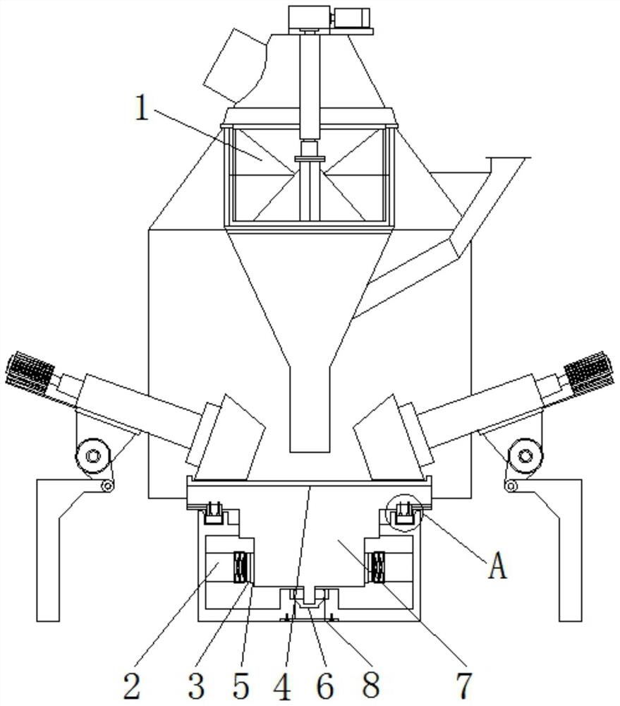
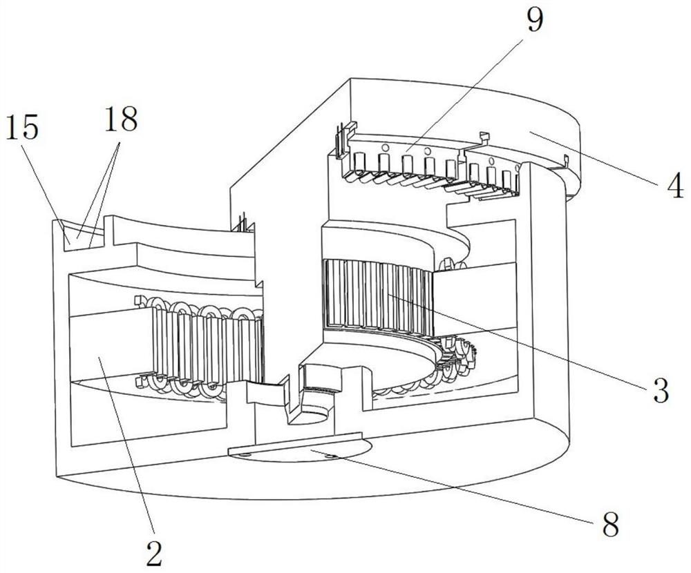
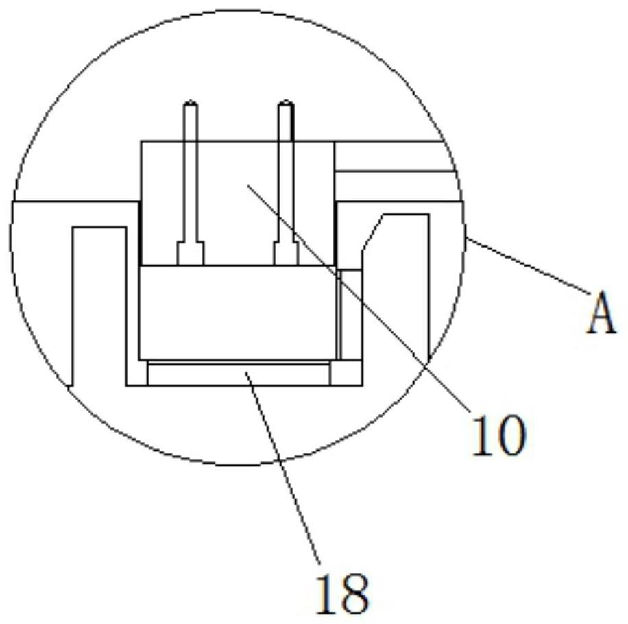
[0045] Describe in detail in conjunction with the accompanying drawings The present invention provides a technical solution: a permanent magnet motor direct-drive vertical mill with a two-way load buffer device, the drive motor of the vertical mill 1 is an annular vertical structure, and the permanent magnet motor directly drive...


PUM


Abstract

The invention discloses a permanent magnet motor direct-driven vertical mill with a bidirectional load buffer device. The permanent magnet motor direct-driven vertical mill comprises a vertical mill, a vertical mill power system, the bidirectional load buffer device, a support frame and a base, wherein the power system comprises a rotor mechanism and an annular stator mechanism; the rotor mechanism is sleeved with the annular stator mechanism; the annular stator mechanism drives the rotor mechanism to rotate; a grinding disc is arranged above the rotor mechanism; a rotary drum is connected with the grinding disc of the vertical mill; the annular stator structure mainly comprises a three-dimensional shell, a motor winding and a base; the base is used for supporting the stator structure and a fixed bearing; and the bidirectional load buffer device is arranged at the circumferential position of the upper end face of the stator structure or the lower end face of the grinding disc, is composed of fan-shaped modules and is spliced into a ring-shaped structure. The bidirectional load buffer device can ensure the relative sliding of the stator structure and the rotor structure, and also can bear the radial and axial bidirectional bearing force from the permanent magnet direct-driven vertical mill.

Description

technical field [0001] The invention relates to the technical field of vertical mills, in particular to a permanent magnet motor direct-drive vertical mill with a bidirectional load buffering device. Background technique [0002] The vertical mill is the key equipment for grinding the material into powder after being crushed. The vertical mill is based on the extensive use of advanced technology at home and abroad, combined with many years of various mills, pulverizers, and ball mills. Advanced production experience, design and development of advanced grinding equipment; it is an ideal equipment for the grinding industry that integrates crushing, drying, grinding, and grading and conveying. Can be widely used in cement, electric power, metallurgy, chemical industry, non-metallic minerals and other industries. It is used to grind lumpy, granular and powdery raw materials into required powdery materials. Before the 1960s, the newly developed vertical mill had an imperfect st...

Claims


Application Information

Patent Timeline
IPC IPC(8): B02C15/00B02C23/00F16F15/02F16F15/04F16F15/06
CPCB02C15/00B02C23/00F16F15/02F16F15/021F16F15/046F16F15/06
Inventor 张炳义尚勤贵冯桂宏卞浩田吴鹏尚金铎高敏陈高敏尚金鸽
Owner 河南全新机电设备有限公司
Why Eureka
Try Eureka