
Waste treatment mechanism of digital control drilling machine

A numerical control drilling machine and waste treatment technology, applied in metal processing machine parts, maintenance and safety accessories, metal processing equipment, etc., can solve the problems of waste treatment, poor quality of waste treatment, easy blockage of waste treatment mechanism, etc., to achieve Prevents clogging and facilitates movement

Pending Publication Date: 2021-12-07
深圳市镇泰数控有限公司
View PDF0 Cites 1 Cited by
  • Summary
  • Abstract
  • Description
  • Claims
  • Application Information

AI Technical Summary

Problems solved by technology

[0004] The object of the present invention is to provide a waste material treatment mechanism of a numerical control drilling machine, which solves the problem that the traditional waste material treatment mechanism generally further pulverizes the waste material, but cannot process the waste material more completely, resulting in poor quality of waste material treatment. , the traditional waste processing mechanism cannot realize the function of uniform feeding, which leads to the problem that the waste processing mechanism is prone to blockage

Method used


Image

  • Waste treatment mechanism of digital control drilling machine
  • Waste treatment mechanism of digital control drilling machine
  • Waste treatment mechanism of digital control drilling machine

Examples


Embodiment Construction

[0025] The following will clearly and completely describe the technical solutions in the embodiments of the present invention with reference to the accompanying drawings in the embodiments of the present invention. Obviously, the described embodiments are only some, not all, embodiments of the present invention. Based on the embodiments of the present invention, all other embodiments obtained by persons of ordinary skill in the art without creative efforts fall within the protection scope of the present invention.

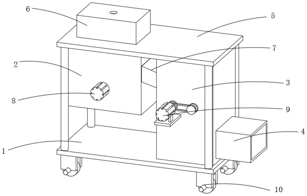
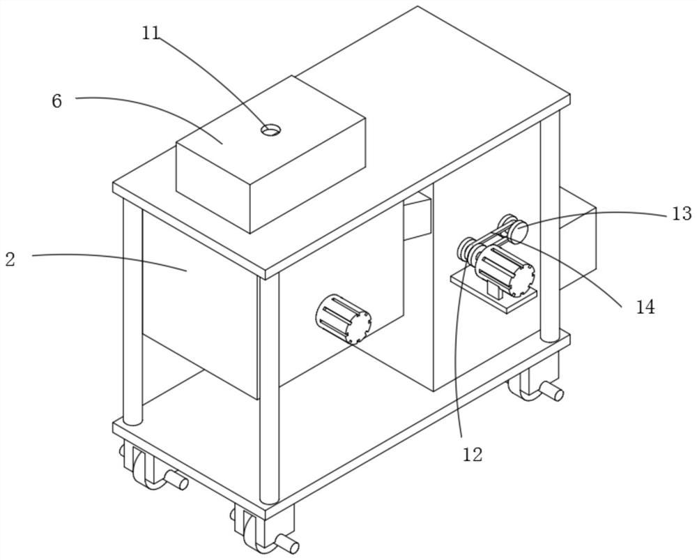
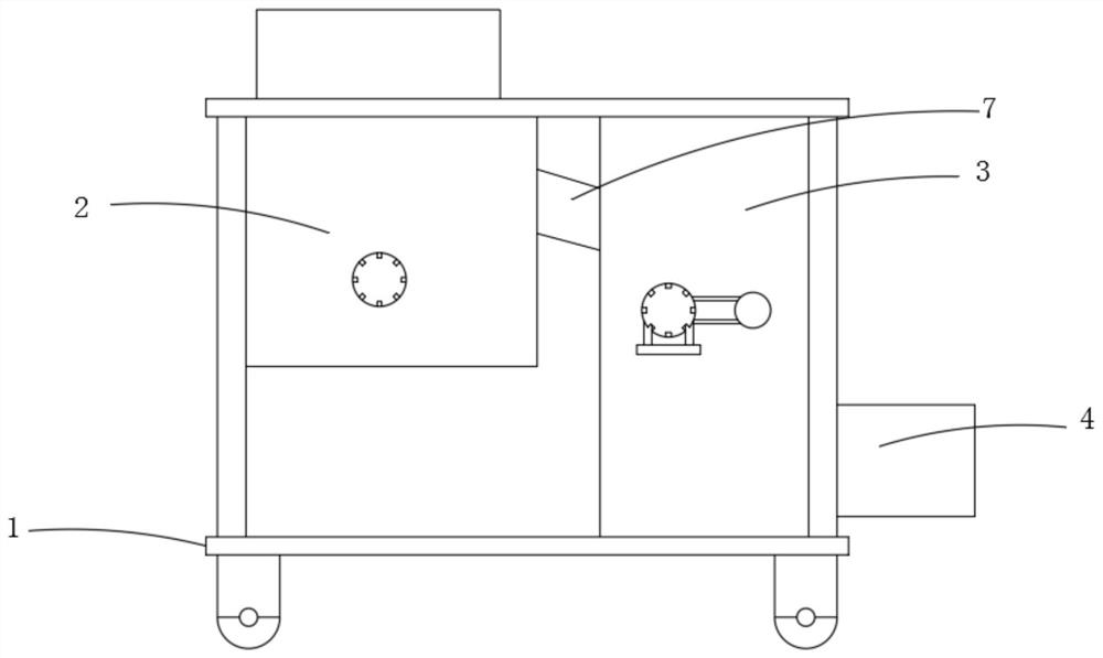
[0026] see Figure 1-6 As shown, the present invention is a waste processing mechanism for a numerical control drilling machine, comprising a bottom plate 1, a material delivery box 2, a treatment box 3, a collection box 4 and a top plate 5, the bottom plate 1 and the top plate 5 are plate structures, and the material delivery box 2, the treatment box 3 and the collection box 4 are box structures, and the inside of the treatment box 3 is equipped with a first pulve...


PUM


Abstract

The invention discloses a waste treatment mechanism of a digital control drilling machine, and relates to the technical field of numerical control machining. The waste treatment mechanism comprises a bottom plate, a material conveying box, a treatment box, a collecting box and a top plate, wherein a first crushing roller, a second crushing roller, a screening net and a reciprocating motor are installed in the treatment box; the reciprocating motor is connected with a threaded rod; a movable threaded sleeve is installed on the peripheral side face of the threaded rod; the movable threaded sleeve is connected with a scraping plate and a smashing rod; a connecting groove is installed in the collecting box; a second spring is installed in the connecting groove and connected with a baffle; and the movable threaded sleeve is in threaded fit with the threaded rod. The movable thread sleeve is arranged to be in threaded fit with the threaded rod, the screening net screens waste which is not completely crushed, the threaded rod rotates, the movable thread sleeve drives the scraping plate to move left and right, waste on the upper surface of the screening net is cleaned, and after the movable thread sleeve moves to one end of the threaded rod, the smashing rod extrudes the baffle, and the scraping plate can push the waste which is not completely crushed into the collecting box for secondary crushing, so that crushing is more complete.

Description

technical field [0001] The invention belongs to the technical field of numerical control machining, and in particular relates to a waste material processing mechanism of a numerical control drilling machine. Background technique [0002] CNC machining refers to a process method for processing parts on CNC machine tools. The process regulations of CNC machine tool processing and traditional machine tool processing are generally consistent, but significant changes have also taken place. A machining method that uses digital information to control the movement of parts and tools. It is an effective way to solve the problems of variable variety, small batch, complex shape and high precision of parts and realize high-efficiency and automatic processing. [0003] When processing parts, it is often necessary to drill the parts, which requires the use of CNC drilling machines. After the drilling machine drills the parts, it is easy to produce a large amount of fertilizer. The tradit...

Claims


Application Information

Patent Timeline
Patent Type & Authority Applications(China)
IPC IPC(8): B23Q11/00
CPCB23Q11/0042
Inventor 姜傲胜李健忠王庆宁刘冬冬
Owner 深圳市镇泰数控有限公司
Learn More