Preparation method of cathode with composite metal layer for rare earth electrolysis

A composite metal layer and cathode technology, applied in the direction of electrodes, electrolysis process, electrolysis components, etc., can solve problems such as service life not exceeding one year, high price, and increased production cost.

Pending Publication Date: 2021-12-07
INNER MONGOLIA METAL MATERIAL RES INST
View PDF0 Cites 2 Cited by
  • Summary
  • Abstract
  • Description
  • Claims
  • Application Information

AI Technical Summary

Problems solved by technology

The entire tungsten cathode is scrapped after being corroded and thinned or broken. Even if the tungsten cathode is turned around and used, its service life still cannot exceed one year
However, tungsten is a rare metal and is expensive. Frequent replacement of tungsten cathodes not only affects production efficiency, but also greatly increases production costs.

Method used


Image

  • Preparation method of cathode with composite metal layer for rare earth electrolysis
  • Preparation method of cathode with composite metal layer for rare earth electrolysis
  • Preparation method of cathode with composite metal layer for rare earth electrolysis

Examples


Embodiment 1

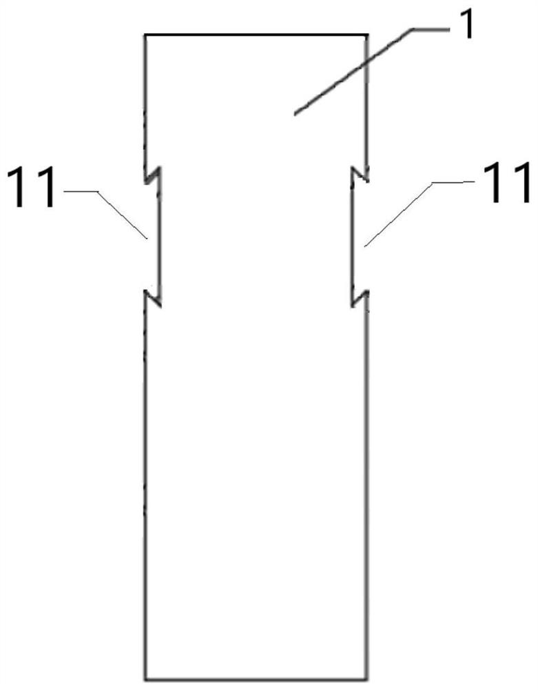
[0054] Such as figure 1 As shown, the corrosion-prone part of the tungsten rod base 1 (that is, the setting area located 120mm below the connection between the upper part of the cathode and the electrolytic equipment to 100mm above the liquid level of the electrolyte) is processed into a groove with an isosceles trapezoidal cross section. Structure 11 (i.e. a dovetail-shaped groove structure), the upper bottom of the isosceles trapezoid is located on the surface of the tungsten rod substrate 1, the lower bottom is parallel to the central axis of the tungsten rod substrate 1, and the length of the upper bottom is less than the length of the lower bottom; The groove structure 11 is arranged along the circumferential direction of the tungsten rod base 1 . The groove structure 11 is located near the end of the tungsten rod base 1 .

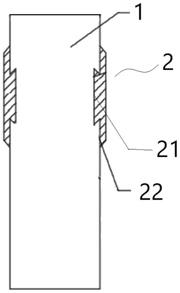
[0055] The mold filling part formed by polystyrene foam that matches the groove structure 1 is packed into the groove structure 11 on the tungsten r...

Embodiment 2

[0061] Except the following difference, all the other are the same as embodiment 1:

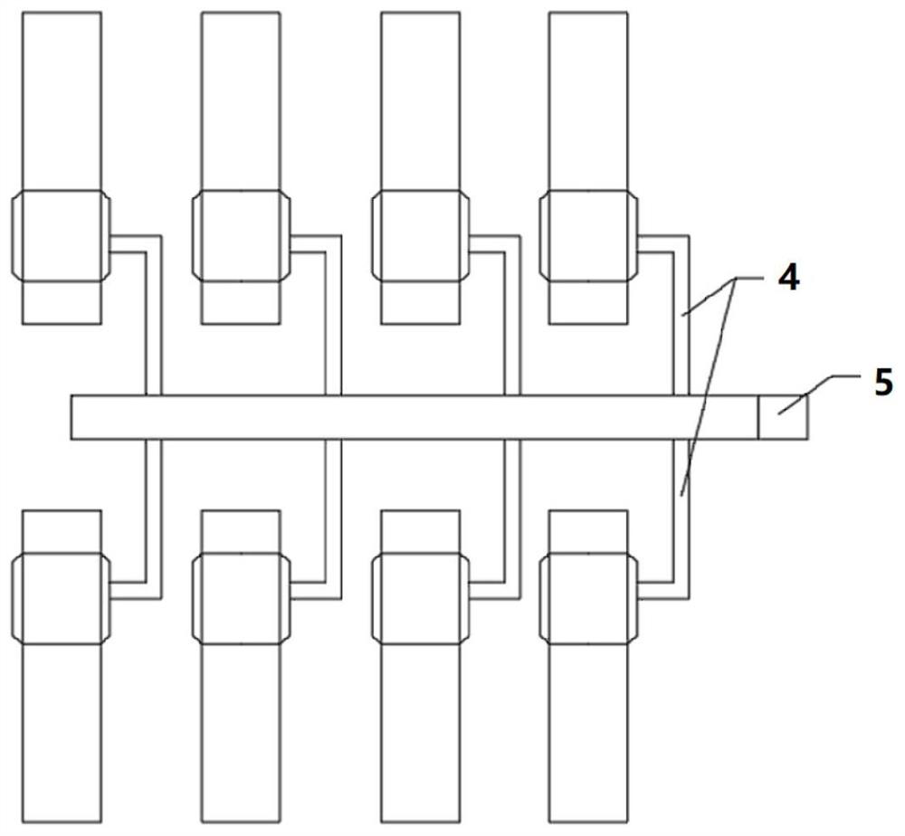
[0062] Place 8 coated tungsten rod substrates containing the model layer in each layer, symmetrically placed on both sides of the runner, the melting temperature is 1630°C, the pouring speed is 17kg / s, and the thickness of the extension of the composite metal layer is 25mm.

[0063] Under the same conditions as in Example 1, the service life of the cathode obtained in this example is 270 days.

Embodiment 3

[0065] Except the following difference, all the other are the same as embodiment 2:

[0066] The total coating thickness of the paint is 2.0mm; the negative pressure of the sand box is -0.02MPa; the melting temperature is 1620°C, the pouring speed is 20kg / s, and the thickness of the extension part of the composite metal layer is 30mm.

[0067] Under the same conditions as in Example 1, the service life of the cathode obtained in this example is 300 days.


PUM

PropertyMeasurementUnit
thicknessaaaaaaaaaa
thicknessaaaaaaaaaa
thicknessaaaaaaaaaa

Abstract

The invention discloses a preparation method of a cathode with a composite metal layer for rare earth electrolysis. The preparation method comprises the following steps: (1) forming a groove structure of which the cross section is an isosceles trapezoid in a set area by using a tungsten rod matrix; (2) preparing a model layer, and obtaining a tungsten rod matrix containing the model layer, wherein the model layer is made of a high-molecular polymer foam material; (3) coating the surface of the model layer with paint, and obtaining the tungsten rod matrix containing the model layer after being coated with the paint; (4) putting the tungsten rod matrix which is coated with the paint and contains the model layer and obtained in the step (3) in a pouring system, and pouring molten metal liquid; and (5) annealing to obtain the cathode with the composite metal layer for rare earth electrolysis. The cathode prepared by the preparation method is long in service life.

Description

technical field [0001] The invention relates to a preparation method of a cathode with a composite metal layer for rare earth electrolysis, in particular to a preparation method of a corrosion-resistant and high-temperature resistant cathode with a composite metal layer for rare earth electrolysis. Background technique [0002] Rare earth, known as "industrial monosodium glutamate", is an important strategic resource in my country and is widely used in various fields. Rare earth elements have strong activity, so it is difficult to carry out reduction preparation by ordinary methods. At present, the most effective method is molten salt electrolysis. [0003] In industrial production, single light rare earth metals and mixed rare earth metals such as lanthanum, cerium, and neodymium are mainly produced by molten salt oxide electrolysis. The production of rare earth metals by molten salt oxide electrolysis requires the use of refractory and corrosion-resistant metal cathodes. ...

Claims


Application Information

Patent Timeline
Patent Type & Authority Applications(China)
IPC IPC(8): C25C7/02C25C3/34
CPCC25C7/025C25C3/34
Inventor 张鸣一高平王昊
Owner INNER MONGOLIA METAL MATERIAL RES INST
Why Eureka
Try Eureka