Supercharge Your Innovation With Domain-Expert AI Agents!

A multi-plate friction-hydraulic composite brake support bridge

A compound brake and friction brake technology, applied in the direction of liquid resistance brakes, brakes, brake components, etc., can solve the difficulty of choosing the installation position of the retarder, the slow response speed of the hydraulic retarder, and the inability to provide braking force in time, etc. problem, to achieve high braking effect and safety, reduce the quality of the whole bridge, and improve the effect of braking

Active Publication Date: 2022-06-21
BEIJING UNIV OF TECH
View PDF10 Cites 0 Cited by
  • Summary
  • Abstract
  • Description
  • Claims
  • Application Information

AI Technical Summary

Problems solved by technology

But for semi-trailer tractors, the installation position selection of the retarder is still a difficult problem
At present, there are mainly two installation schemes for the hydraulic retarder of the semi-trailer tractor. One is to install it in the drive train of the trailer, but the weight of the semi-trailer tractor is concentrated on the trailer part, and the inertia of the trailer part is relatively large. Too large can easily lead to vehicle instability
The other is to install the hydraulic retarder in the middle of the non-drive axle of the trailer, and remove the mechanical brake of the original axle. Although this solution guarantees braking safety to a certain extent, due to the response speed of the hydraulic retarder Slow, so when the vehicle needs emergency braking, the bridge cannot provide braking force in time, and the emergency braking effect is poor

Method used


Image

  • A multi-plate friction-hydraulic composite brake support bridge
  • A multi-plate friction-hydraulic composite brake support bridge
  • A multi-plate friction-hydraulic composite brake support bridge

Examples


Embodiment Construction

[0027] In order to make the purpose, technical solutions and advantages of the present invention clearer, the present invention will be described in further detail below with reference to the accompanying drawings.

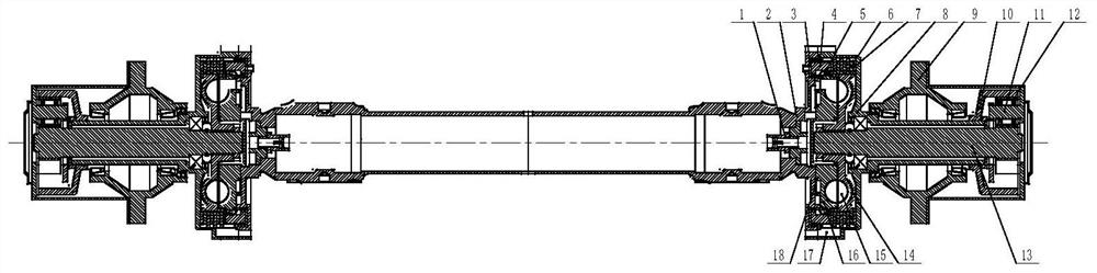
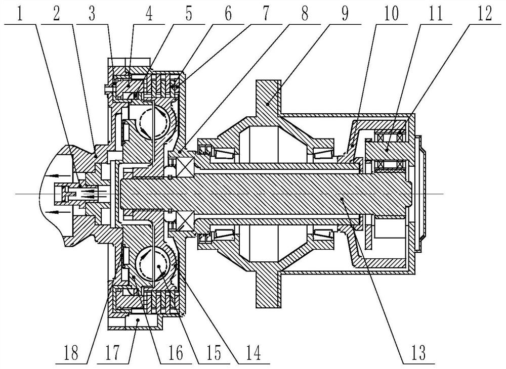
[0028] like figure 1 As shown, it is an assembly diagram of a multi-plate friction-hydraulic composite brake support bridge of the present invention, including a support bridge part, a hydraulic retarder part, a multi-plate friction brake part, and a speed increasing mechanism part.

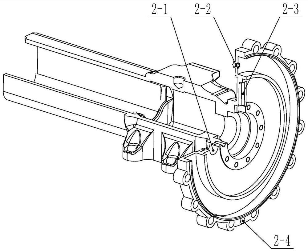
[0029] The supporting bridge part includes a supporting axle housing 2, a wheel side axle housing 8 and a wheel hub 9. The supporting axle housing 2 is provided with a working fluid inlet 2-1 and an air inlet 2-2 on the side close to the wheel side. The liquid inlet 2-1 enters the liquid inlet channel 16-1, and the water channel isolation plate 18 separates the liquid outlet channel 2-3 from the liquid inlet channel 16-1, and the two do not interfere with each other. The air inlet 2-...


PUM


Abstract

The invention discloses a multi-plate friction-hydraulic composite braking support bridge, which comprises a support bridge part, a hydraulic retarder part, a multi-plate friction brake part and a speed-increasing mechanism part. The composite brake support bridge highly integrates the hydraulic retarder and the multi-disc friction brake at the wheel side, replacing the position of the original drum brake and its actuator, effectively reducing the weight of the whole bridge. The multi-plate friction brake is located on the outer ring of the hydraulic retarder. Through the control of the air source, a speed-up mechanism is added to the wheel side to improve the braking effect of the hydraulic retarder and the friction brake. The working medium of the composite brake support bridge is hydraulic to provide the braking effect and at the same time enter the multi-disc friction brake to immerse the friction discs to increase the heat dissipation effect. When braking for a long time, the hydraulic retarder provides the braking torque, and when braking in an emergency, it relies on multi-plate friction brakes with fast response to brake, which improves the braking efficiency and driving safety of the semi-trailer tractor.

Description

technical field [0001] The invention belongs to the technical field of automobile auxiliary braking, and in particular relates to a multi-plate friction-hydraulic composite brake support bridge. Background technique [0002] In recent years, my country's road transportation industry has developed rapidly. Semi-trailer tractors have played a crucial role in road transportation due to their advantages of large load capacity, high efficiency and low logistics cost. However, due to the complex road conditions in my country and many long downhill sections, it is difficult to ensure the braking safety of the semi-trailer tractor when the semi-trailer tractor is downhill for a long time. Therefore, more and more semi-trailer tractors choose to install retarders. Wait for the auxiliary braking device to relieve the burden on the braking system. [0003] The hydraulic retarder is light in weight, small in size, and has excellent continuous braking performance, which can meet the need...

Claims


Application Information

Patent Timeline
Patent Type & Authority Patents(China)
IPC IPC(8): F16D63/00F16D57/02F16D55/24F16D65/18F16D65/853F16D65/78B60T1/087B60T1/06B60K17/04F16D121/04
CPCF16D63/00F16D57/02F16D57/005F16D55/24F16D65/18F16D65/853F16D65/78B60T1/087B60T1/065B60K17/046F16D2121/04F16D2065/782
Inventor 李德胜陈伟鑫高志伟朱冠林
Owner BEIJING UNIV OF TECH
Features
  • R&D
  • Intellectual Property
  • Life Sciences
  • Materials
  • Tech Scout
  • Unparalleled Data Quality
  • Higher Quality Content
  • 60% Fewer Hallucinations
Learn More