Laboratory sample identification system based on RFID technology

An identification system, RFID tag technology, applied in the direction of collaborative operation devices, electromagnetic radiation induction, instruments, etc., can solve the problems of easy falling of tags and confusion of samples, and achieve the effect of accurate identification and cost reduction.

Pending Publication Date: 2021-12-10
DIGITALHORNS NETWORK TECH SUZHOU CO LTD
View PDF0 Cites 4 Cited by
  • Summary
  • Abstract
  • Description
  • Claims
  • Application Information

AI Technical Summary

Problems solved by technology

[0004] According to this principle, this technology can also be applied to other industries, such as large-scale laboratories; in large-scale experiments, due to the large amount of experiments per day, there are relatively many experimental samples, and some of these samples need to be refrigerated. Some of them can be placed at room temperature, and some of them need to be heated up in an incubator; but no matter which one they are, they need to be pl

Method used


Image

  • Laboratory sample identification system based on RFID technology
  • Laboratory sample identification system based on RFID technology

Examples


Embodiment

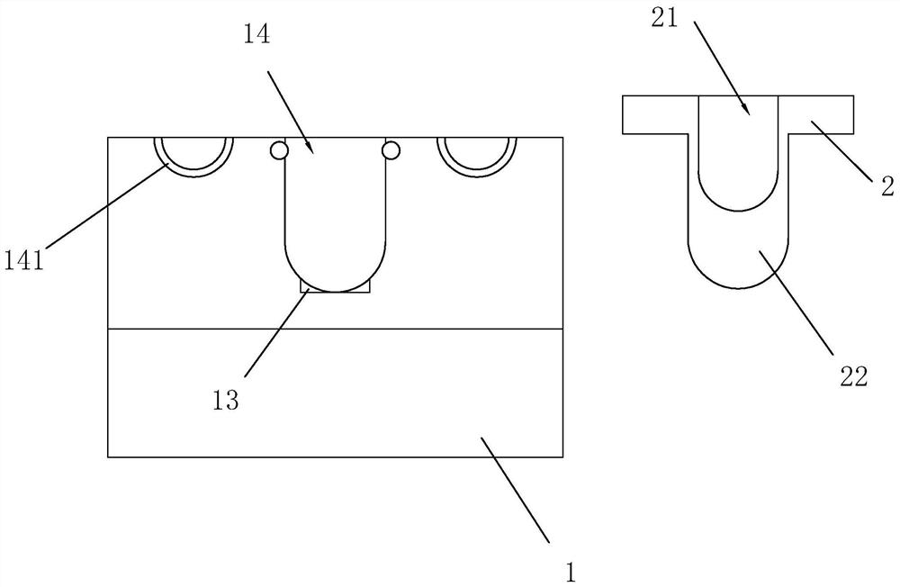
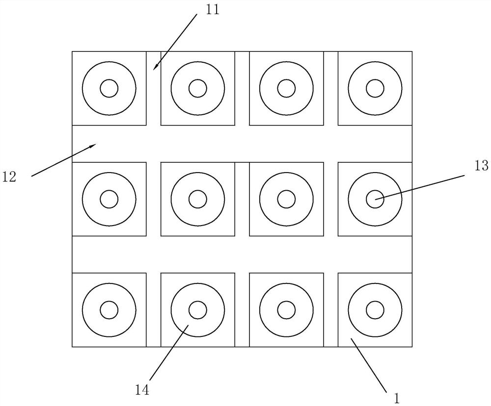
[0031] A laboratory sample identification system based on RFID technology, such as figure 1 , 2 As shown, it includes a test tube tray 1 and a test tube holder 2. The test tube holder 2 is used to fix the test tube or some other glass containers, and the test tube holder 2 equipped with chemical instruments such as test tubes is placed on the test tube tray 1; according to actual use needs , the test tube tray 1 can be placed on the test bench, or on some shelves, or in a refrigerator or an incubator.

[0032] Such as figure 1 , 2 As shown, the surface of the placing tray 1 is recessed and provided with several longitudinal grooves 11 and transverse grooves 12, the longitudinal grooves 11 and the transverse grooves 12 divide the surface of the placing tray 1 into several squares, and each square is provided with a micro sensor Weigher 13; the surface of the grid is depressed to form a card slot 14, and the surface of the test tube holder 2 is provided with an arc-shaped gro...


PUM


Abstract

The invention relates to a laboratory sample identification system based on an RFID technology, the system comprises a background server and terminal equipment connected to the background server, and further comprises a total read-write system connected with the terminal equipment; the system further comprises a plurality of test tube supports, and RFID tags are arranged on the test tube supports; the system further comprises a placement tray, an RFID sensing system is arranged on the placement tray, and an RFID reader reads the content on the RFID tag and uploads the content to the background server; the system also comprises an RFID read-write system, and the RFID read-write system comprises an information obtaining system and an RFID write-in system; the information obtaining system scans and reads the RFID tag and then enters the RFID write-in system, and the RFID write-in system stores data information into the RFID tag; reading and positioning of the RFID test tubes in the single grid of each matrix are realized through RF Switch control; the RFID tag is installed at the bottom of the test tube support or surrounds the wall of the test tubes, the RFID antenna is arranged below the test tube groove at the bottom of the clamping groove and is connected with the RF Switch and the reader through a feeder line, and batch checking and accurate positioning are achieved through reading and writing.

Description

technical field [0001] The invention relates to a positioning system, in particular to a laboratory sample identification system based on RFID technology. Background technique [0002] RFID technology (Radio Frequency Identification) is a non-contact automatic identification technology. Its principle is to conduct non-contact data communication between the reader and the tag to achieve the purpose of identifying the target. In recent years, RFID technology has developed rapidly. Has achieved a wide range of applications. Typical applications include animal chips, car chip anti-theft devices, access control, parking lot control, production line automation, material management, etc.; radio frequency identification technology through radio waves without contact with fast information exchange and storage technology, through wireless communication Combined with data access technology, and then connected to the database system to achieve non-contact two-way communication, so as to...

Claims


Application Information

Patent Timeline
IPC IPC(8): G06K17/00G06K7/10
CPCG06K17/0029G06K7/10297
Inventor 赵旭
Owner DIGITALHORNS NETWORK TECH SUZHOU CO LTD
Why Eureka
Try Eureka