Rotary type transnasal aneurysm clamp

A kind of aneurysm clip and rotary technology, which is applied in the field of medical devices, can solve the problems that cannot meet the basic functions of intracranial aneurysm surgery, and achieve the effect of occupying a small space

Pending Publication Date: 2021-12-17
中国人民解放军总医院第六医学中心
View PDF15 Cites 0 Cited by
  • Summary
  • Abstract
  • Description
  • Claims
  • Application Information

AI Technical Summary

Problems solved by technology

However, the above-mentioned instruments are usually a simple modification of the existing aneurysm clamp without changing the gripping method of the existing clamp body. At the same time,

Method used


Image

  • Rotary type transnasal aneurysm clamp
  • Rotary type transnasal aneurysm clamp

Examples


Embodiment 1

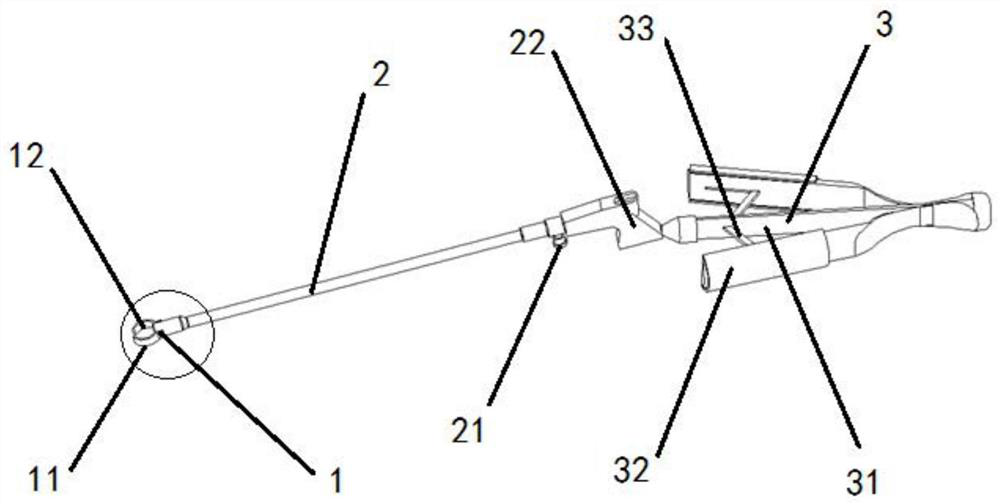
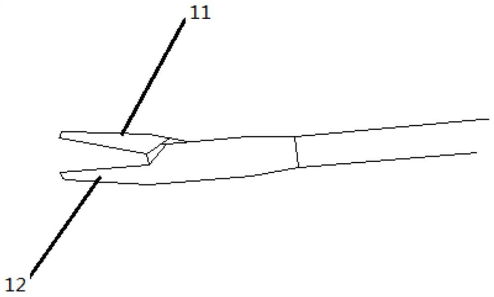
[0027] A hospital uses a new nasal aneurysm clamp for cerebral aneurysm. See figure 1 , Rotary nasal aneurysms clamp, including a clamp head, a jaw rod, and a clamp. The whole is made of stainless steel or titanium alloy, and the front is a clamp head, and the clamp head is connected to the gripper of the grip. The clamp head includes a clamping head for clamping aneurysm clamp, a clamping head using a moving - static bonding mode, see attached figure 2 , Including movable brake plates and relatively stationary sage. The movable jaw and the sideline are basically curved, which make up a circular clamping portion, which is convenient to clamp the aneurysm. The circular portion of the movable jaw and the sideline is about 10 mm. The inside of the movable flap and the sideline is used to use flexible resin material to do anti-skid treatment, and the opposite surface is provided. The moving flap is connected to a static panel through a pin. The tail of the sideline is fixed to the hol...

Embodiment 2

[0030] A hospital is subjected to micro-aneurotic pulleration surgery under neuroboscope. The surgical field of view is very small, the traditional linear surgery clamp, the doctor's wrist is very powerful, and the surgery is often deformed, affecting the surgical effect. At the same time, the linear hand surgery occurs occurs the field of view and affects the accuracy of the action. Therefore, it is improved on the basis of the original nasal aneurysm clamp, so that the jaw rod axis is an angle with the jaw axis. In the present embodiment, the angle inclined downward is 15 °.

[0031] In practical applications, the trapezoidal boss can be set to movable, by adjusting the trapezoidal boss, achieving the angular change in the jaw rod axis and the jaw axis, and the angle can be disposed between 20 ° ~ -20 °.

Embodiment 3

[0033] A teaching case requires nasal operation on the head. At this time, the sinus slope of the sponge sinus, and the bed split ICA is an ideal part of establishing proximal control.

[0034] Bed germlers are located in an important neuroplastic structure, one of the most challenging blood diseases that may encounter in neurosurgeons. Due to the unique anatomical structure of the region, surgery enters the starting point of the intraocular artery (OPHA), a pituitary upper artery (SHA), and a carotid nest. Craniotic surgery for the treatment of bedrosis has caused complications and aneurysm residual / recurrence than other parts of the aneurysms due to other parts. Perhaps this is the main reason why the intervention technology is relatively popular in treating these difficulties. However, compared to interventional techniques, it is still a popular choice due to their persistence and effectiveness.

[0035] Clamping the margin sinus ICA has the risk of damage trigeminal nerve an...


PUM


Abstract

A rotary type transnasal aneurysm clamp comprises a clamp head, a clamp rod and a clamp handle, the clamp head comprises a clamping head, the clamp handle comprises a rotary protrusion, and the clamp handle is only provided with a supporting column. According to the needle holding clamp, a pen type structure is adopted, the occupied space is small, the needle holding clamp is more suitable for the narrow environment clamped by a nasal endoscope, the clamp rod can rotate by 360 degrees, the opening and closing degree of the clamp head can be freely set, the needle holding clamp can be used in various different aneurysm operations, rotation of the clamp rod and opening and closing of the clamp head can be completed by one hand, a doctor can operate equipment such as the endoscope with the other hand, and the nasal endoscopic surgery can be conveniently carried out.

Description

Technical field [0001] The present invention relates to a medical device, and more particularly to a rotary nasal aneurysm clamp used in the intraudioboscope. Background technique [0002] The intracranial aneurysm is mostly abnormal bulge that occurs on the intracranial arterial tube wall, which is the first cause of the subarachnoid hemorrhage. In the cerebrovascular accident, second only to cerebral thrombosis and high blood pressure, ranking three. The incidence of Chinese people is approximately 3-4%. The residual residual residual caused by a patient patient. [0003] The treatment of intracranial aneurysms can be treated by craniotomy and interventional embolization. The two methods have their excellent disadvantages. In recent years, endoscopic inner mirror into the third surgical manner of the treatment of aneurysms, for a specific site (such as the aneurysms of the cervical artery bed and the bed, the former traffic artery, the vertebral-substrate artery, etc.), Direct ...

Claims


Application Information

Patent Timeline
IPC IPC(8): A61B17/29A61B17/24
CPCA61B17/24A61B17/29A61B2017/2929
Inventor 周春辉
Owner 中国人民解放军总医院第六医学中心
Why Eureka
Try Eureka