Maximum regenerative braking torque optimization control method for permanent magnet synchronous motor driving system

A permanent magnet synchronous motor, braking torque technology, applied in motor control, motor generator control, AC motor control and other directions, can solve problems such as low acquisition efficiency, complex three-dimensional tables, affecting the stable operation of the motor system, and achieve control Good real-time effect

Pending Publication Date: 2021-12-17
INST OF ELECTRICAL ENG CHINESE ACAD OF SCI
View PDF2 Cites 0 Cited by
  • Summary
  • Abstract
  • Description
  • Claims
  • Application Information

AI Technical Summary

Problems solved by technology

The accuracy of the aforementioned "torque-speed-current" table directly affects the torque output capability of the permanent magnet motor, such as torque accuracy, maximum torque output, and may even affect the normal operation of the motor controller. Stable operation of the motor system
The three-dimensional table is more complicated and less practical. As a technical improvement, the patent 201811184414 "a current i based on the permanent magnet motor parameter table d i q The automatic generation method of the table” proposes a method that provides a current i based on the parameter table of the permanent magnet motor d i q The method of automatic generation of two-dimensi

Method used


Image

  • Maximum regenerative braking torque optimization control method for permanent magnet synchronous motor driving system
  • Maximum regenerative braking torque optimization control method for permanent magnet synchronous motor driving system
  • Maximum regenerative braking torque optimization control method for permanent magnet synchronous motor driving system

Examples


Embodiment Construction

[0063] The present invention is further described below with reference to the accompanying drawings and specific embodiments.

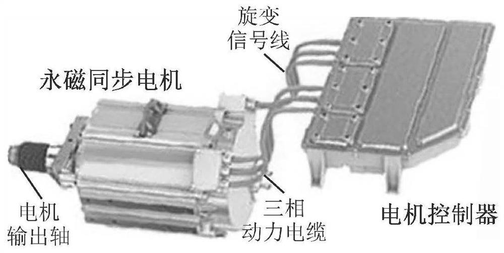
[0064] The embodiment of the permanent magnet synchronous motor drive system of the present invention mainly includes two parts, a permanent magnet synchronous motor and a motor controller, figure 1 It is a schematic diagram of the connection relationship between the permanent magnet synchronous motor and the motor controller. like figure 1 As shown, the permanent magnet synchronous motor is connected to the motor controller through a three-phase power cable, a resolver is installed at the outlet end of the permanent magnet synchronous motor, and the signal output end of the resolver is connected to the signal input end of the motor controller through the resolver signal line , to complete the measurement of the rotor position and speed of the motor in the motor controller. When the permanent magnet synchronous motor drive system works in the regenera...


PUM


Abstract

The invention provides a maximum regenerative braking torque optimization control method for a permanent magnet synchronous motor driving system. According to the invention, by comprehensively considering the T-omega external characteristic of a permanent magnet synchronous motor and the constraint of the capacity of a motor controller on the maximum braking torque output by the motor, through the design of the unit power factor control law of the permanent magnet synchronous motor and the solution of a change law of motor inductors Ld and Lq along with stator currents id and iq, real-time calculation of a current instruction value corresponding to the maximum braking torque is carried out based on an online calculation mode, accurate control of the maximum braking torque of a permanent magnet motor driving system in a full rotation speed range is completed, and the regenerative braking efficiency of the permanent magnet synchronous motor driving system is optimized; and the maximum torque optimization control method is completed based on a real-time calculation mode, has the advantages that the control real-time performance is good, and the control precision is not influenced by the inductance change in the operation process of the permanent magnet synchronous motor, and has obvious advantages in the aspects of control precision, usability and the like compared with the prior art.

Description

technical field [0001] The invention relates to the field of permanent magnet synchronous motor control, in particular to a method for optimizing the maximum regenerative braking torque of a permanent magnet synchronous motor drive system. Background technique [0002] Permanent magnet motors have the characteristics of high energy storage density, high power density and long service life, and are widely used in new energy vehicle drives, flywheel energy storage and other fields. The permanent magnet motor drive system includes two parts, the permanent magnet motor and the motor controller, which together complete the electromechanical energy conversion process. According to the different flow directions of the energy flow, its working process can be divided into two cases, namely: electric operation, corresponding to the conversion process of electrical energy to mechanical energy, the permanent magnet motor drive system absorbs electrical energy from the power supply side ...

Claims


Application Information

Patent Timeline
IPC IPC(8): H02P21/36H02P21/30H02P21/00H02P21/16H02P21/22H02P6/24H02P25/026H02P27/08
CPCH02P21/36H02P21/30H02P21/0003H02P21/16H02P21/22H02P6/24H02P25/026H02P27/085H02P2207/05
Inventor 张剑温旭辉彭萌李文善高雪飞颜朝鹏
Owner INST OF ELECTRICAL ENG CHINESE ACAD OF SCI
Why Eureka
Try Eureka